
Welding method for multi-spot welding with welding wire equally divided welding head

A welding method and welding head technology, which is applied in the field of wire and cable welding devices, can solve problems such as long welding heating time, deformation, and low welding efficiency, and achieve the effects of shortening welding time, concise process steps, and improving welding quality

Active Publication Date: 2016-03-23
HUIZHOU DEHONG TECH CO LTD
View PDF6 Cites 0 Cited by
  • Summary
  • Abstract
  • Description
  • Claims
  • Application Information

AI Technical Summary

Problems solved by technology

This welding method has at least the following deficiencies: one is that the welding quality is affected because the contact surface between the conductor and the welding head is in a state of no tin material; Therefore, the welding heating time is long, the welding efficiency is low, and because the conductor is heated for a long time, the outer covering (insulation coating) on ​​the conductor is deformed by heat transfer and heat radiation damage; There is no temperature during the period when the pressure is in place, so it is easy to cause the solder to be squeezed and spread out, resulting in a "bridging" phenomenon of adjacent conductors at the solder joint after welding; performance characteristics
[0004] If the solder placed on the pad (i.e. placed under the conductor) in the prior art can be introduced from between the soldering head and the conductor and the solder is evenly divided by the soldering head, then the aforementioned technical problems can be basically eliminated. , but must rely on a well-structured welding head
For this reason, the applicant has searched the literature, but there is no corresponding technical revelation in the published patents and non-patent literature

Method used


Image

  • Welding method for multi-spot welding with welding wire equally divided welding head
  • Welding method for multi-spot welding with welding wire equally divided welding head
  • Welding method for multi-spot welding with welding wire equally divided welding head

Examples


Embodiment 1

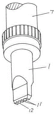
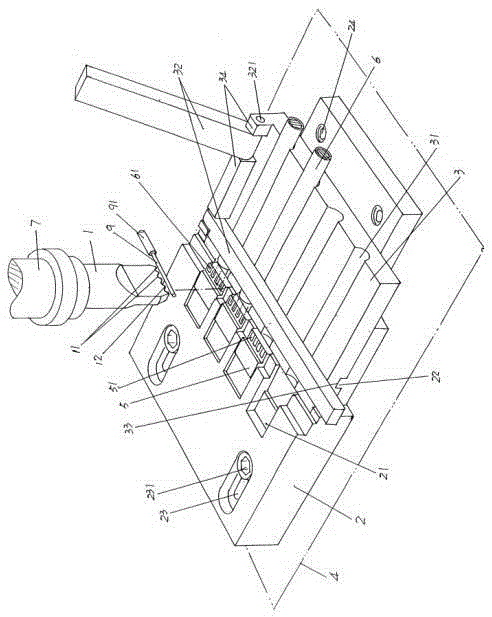
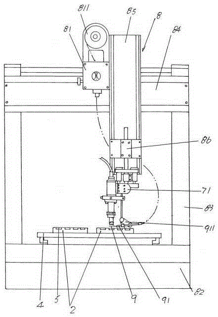
[0022] please see Figure 1 to Figure 3 , the conductor 61 of the wire 6 and the welding point 51 of the pad 5 implement the welding process as follows:

[0023] A) Equipped with a fixture structure consisting of figure 2 Schematically, it includes a base plate 2 and a wire positioning plate 3, the base plate 2 is fixed on the welding workbench 4, and the base plate 2 is facing upwards and at a position corresponding to the long side direction of the wire positioning plate 3 in a spaced state. There is a pad accommodating cavity 21, and the wire positioning plate 3 is positioned on the right end of the base plate 2 at a position corresponding to the right side of the pad accommodating cavity 21, and is parallel to the short side of the wire positioning plate 3 on the wire positioning plate 3 The direction is to set up wire embedding grooves 31 in a spaced state, the number of wire embedding grooves 31 is equal to the number of pad accommodation cavities 21 and the position c...

Embodiment 2

[0029] Only change the dwell time of the welding head body 1 on the conductor 61 in step D) to 0.2 seconds, and the rest are the same as the description of the first embodiment.

Embodiment 3

[0031] Only change the dwell time of the welding head body 1 on the conductor 61 in step D) to 0.4 seconds, and the rest are the same as the description of the first embodiment.


PUM


Abstract

The invention relates to a welding wire equalization welding head for multi-welding-spot welding and a welding method, which belong to the technical field of a wire and cable welding device. The welding wire equalization welding head comprises a welding head body, and is characterized in that the end surface of one end, facing downwards when in use, of the welding head body is provided with a plurality of conductor accommodating valleys which are identical to the amount of conductors to be welded in one step at intervals along the length direction of the end surface, and a projection area between every two adjacent conductor accommodating valleys respectively forms a welding wire equalization edge for segmenting a welding wire. By adopting the welding wire equalization welding head and the welding method, the welding quality of the conductor and a welding disc can be improved, the welding time is shortened, the welding efficiency is improved, and the welding material is prevented from being scattered when the welding head body is pressed downwards, and the uniformity and consistency of welding spots can be guaranteed; the process step is simple, convenience in operation is realized, and not only can the application in the industry be satisfied, but also the technical effect of the welding head body can be guaranteed.

Description

technical field [0001] The invention belongs to the technical field of wire and cable welding devices, and in particular relates to a welding wire equalizing welding head for multi-spot welding, and also relates to a welding method thereof. Background technique [0002] The multi-solder spot welding mentioned above refers to welding the conductor ends exposed after removing the insulating coating from multiple core wires separated from a wire (also known as a cable) to the solder joints on the pad at the same time. , The industry is used to calling this welding method "multi-PIN" welding. For the concept of pads, please refer to the "Printed Board Acceptability IPC-A600H" technical specification. [0003] With the release and continuous upgrading of relevant instructions surrounding high-speed interfaces such as high-definition multimedia interfaces, the design and manufacturing technology of high-speed transmission data lines has been continuously improved, adapting to the...

Claims


Application Information

Patent Timeline
Patent Type & Authority Patents(China)
IPC IPC(8): B23K3/00B23K3/08
CPCB23K3/063B23K3/08B23K2101/38
Inventor 李江李荣耀
Owner HUIZHOU DEHONG TECH CO LTD
Learn More