Testing device and method applicable for spacecraft high-stability pointing control
A space vehicle, a high-stability technology, applied to the simulation device of space navigation conditions, transportation and packaging, space navigation equipment, etc.
- Summary
- Abstract
- Description
- Claims
- Application Information
AI Technical Summary
Problems solved by technology
Method used
Image
Examples
Embodiment 1
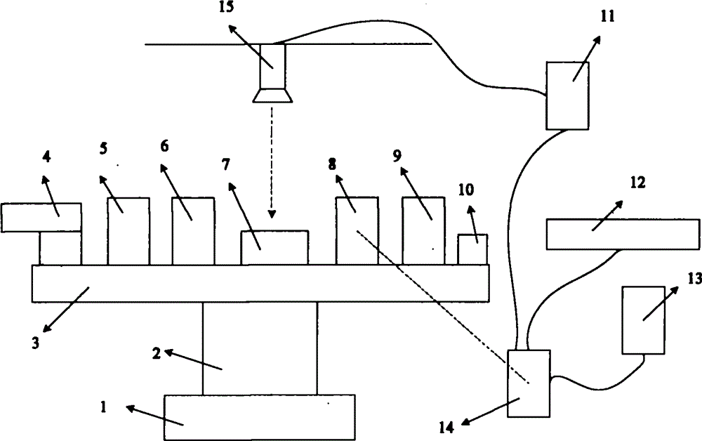
[0022] Such as figure 1 As shown, a high-stability pointing control test device suitable for space vehicles includes a base 1, an air bearing 2, an instrument platform 3, an aircraft pointing unit 4, an aircraft attitude control unit 5, and a data command sending and receiving system 6 on the platform. Marking point 7, target probe unit 8, reflective prism 9, reaction momentum wheel system 10, image processing unit 11, photoelectric autocollimator 12, laser tracker 13, off-stage data command sending and receiving system 14 and camera 15; its features That is, the lower end of the air bearing 2 is installed on the base 1, the upper end of the air bearing 2 is fixedly connected with the instrument platform 3, the target measuring head unit 8, the marker point 7, the aircraft attitude control unit 5, the reflecting prism 9, and the aircraft pointing unit 4 1. On-stage data command transceiving system 6 and reaction momentum wheel system 10 are installed on instrument platform 3, ...
Embodiment 2
[0024]A high-stability pointing control test method suitable for space vehicles, the specific steps are as follows:
[0025] Step 1: Confirm the final expected orientation and initial position of the aircraft pointing unit 4 on the instrument platform 3 according to the test target, install the photoelectric autocollimator 12 according to the final orientation position and the position of the reflecting prism 9, and ensure that the instrument platform 3 When the upper aircraft pointing unit 4 moves to the vicinity of the final desired pointing, the reflective prism 9 can enter the effective field of view of the photoelectric autocollimator 12;
[0026] Step 2: Power on the whole device and supply air to the air bearing 2, and move the aircraft pointing unit 4 on the instrument platform 3 to the initial position required for the test;
[0027] Step 3: Confirm that the target probe unit 8 is in the field of view of the laser tracker 13, and the marker point 7 should not be block...
Embodiment 3
[0035] The pose measurement technology of the air bearing table is explained as follows:
[0036] For the single-axis air bearing table, the 360° full-range measurement can be completed by the camera and its image processing unit with the marker point, or it can be completed by the grating measurement system installed on the axis of the single-axis air bearing table, medium range (±60°) It can be completed by a laser tracker, and a photoelectric autocollimator for high-precision measurement in a small range (typically ±1800 arc seconds), or it can be completed by a grating measurement system;
[0037] For the three-axis air bearing table, the angle measurement can be completed by the camera and its image processing unit in conjunction with the marker points during the 360° full range of motion (for details, please refer to the patent "Binocular Stereo Vision Measuring Device for Three-axis Air Bearing Table Attitude Angle and Its Measurement method", the application number is ...
PUM
 Abstract
Description
Claims
Application Information
 - R&D
- Intellectual Property
- Life Sciences
- Materials
- Tech Scout
- Unparalleled Data Quality
- Higher Quality Content
- 60% Fewer Hallucinations
Browse by: Latest US Patents, China's latest patents, Technical Efficacy Thesaurus, Application Domain, Technology Topic, Popular Technical Reports.
© 2025 PatSnap. All rights reserved.Legal|Privacy policy|Modern Slavery Act Transparency Statement|Sitemap|About US| Contact US: help@patsnap.com

