
Mine vertical shaft/sieve shaft well wall structure and controllable dewatering method thereof

A shaft wall and shaft technology, which is used in drainage, shaft equipment, mining equipment, etc., can solve the problems of long shaft lifting time, difficulty in forming curtains, and potential safety hazards, so as to eliminate long-term erosion, prolong service life, and reduce shaft wall. The effect of stress

Active Publication Date: 2015-03-04
CHINA UNIV OF MINING & TECH
View PDF7 Cites 7 Cited by
  • Summary
  • Abstract
  • Description
  • Claims
  • Application Information

AI Technical Summary

Problems solved by technology

The above engineering measures are mainly controlled by the idea of ​​water blocking, which has obvious effects in the short term. As the groundwater erodes the slurry material, the phenomenon of water splashing will gradually intensify, and at the same time, the water pressure acting on the well wall will not be reduced.
In addition, measure (1) takes a long time to lift the wellbore, and there are potential safety hazards for grouting after the well wall has been broken; measure (2) is a large amount of work and a long construction period, which may exist when the buildings around the wellhead affect the grouting hole layout. The problem that the curtain is difficult to form; also there are safety hazards for the cracked well wall grouting

Method used


Image

  • Mine vertical shaft/sieve shaft well wall structure and controllable dewatering method thereof
  • Mine vertical shaft/sieve shaft well wall structure and controllable dewatering method thereof
  • Mine vertical shaft/sieve shaft well wall structure and controllable dewatering method thereof

Examples


Embodiment

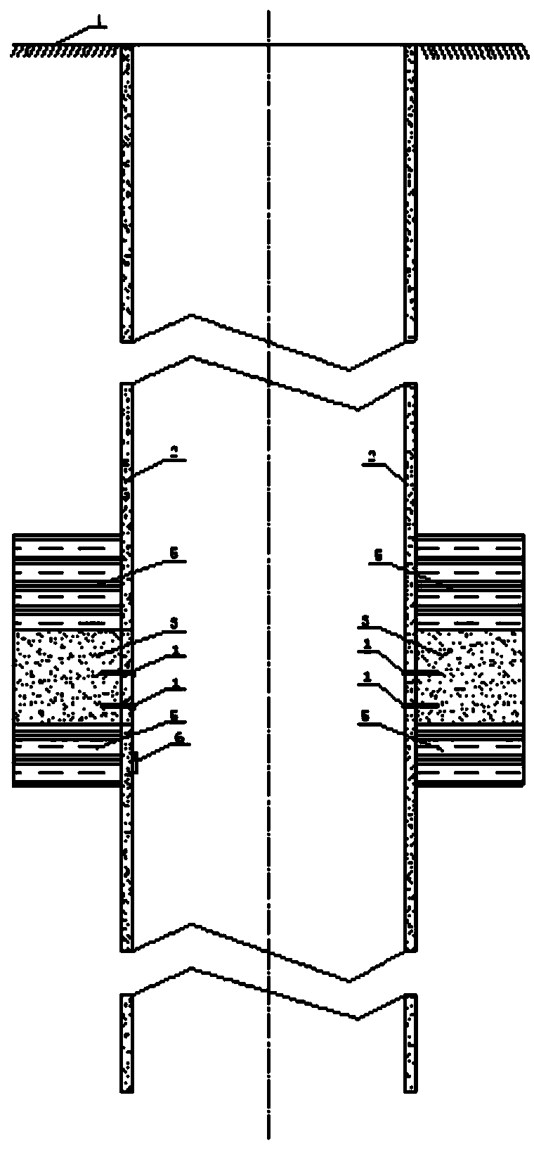
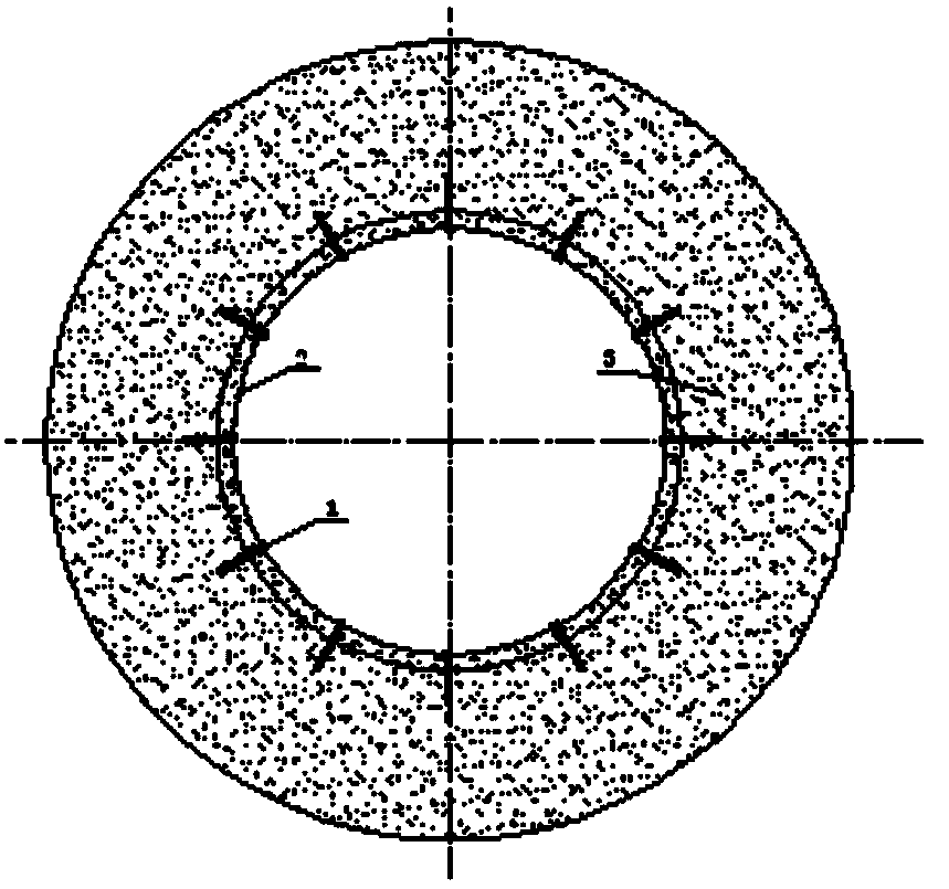
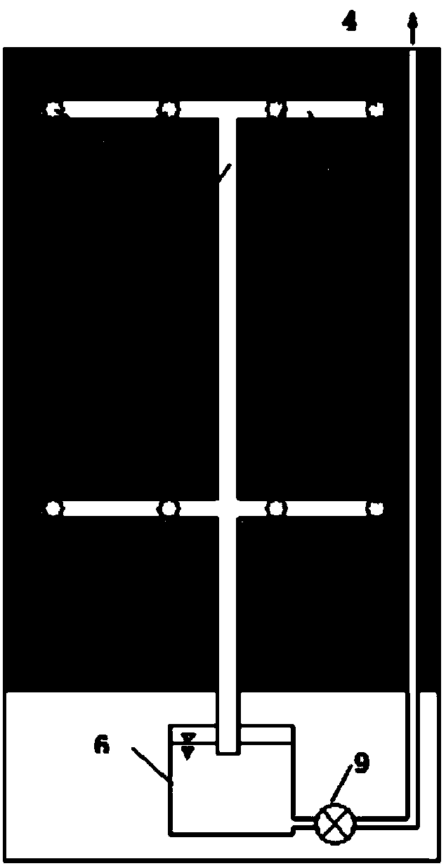
[0026] Embodiment: Screen Well Wall Structure Install intelligent control dredging water pipes on the screen well wall, the intelligent control dredging water pipes are composed of dredging water pipe 1, horizontal water diversion pipe 7, dredging main pipe 8, water collection tank 6 and water pump 9 Screen well wall structure, the horizontal water diversion pipe 7 has multiple layers, arranged horizontally on the well wall, the dredging water pipe 1 has multiple roots, one end communicates with the horizontal water diversion pipe 7, and the other end extends radially into the well wall; the dredging main pipe 8 communicates with the horizontal water diversion pipe 7 of each floor, and the bottom end communicates with the water collection tank 6. An automatic drainage pump 9 is installed on the water collection tank to discharge the water collected in the water collection tank to the outside of the well in time to form water drainage, Hydrophobic systems for control, collection...


PUM


Abstract

The invention discloses a mine vertical shaft / sieve shaft well wall structure and a controllable dewatering method thereof, and belongs to a mine vertical shaft well wall structure and a dewatering method thereof. Multiple layers of horizontal water guide pipes are arranged on the sieve shaft well wall structure, and are horizontally arranged on the well wall; multiple water dredging pipes are arranged; one ends of the water dredging pipes are communicated with the horizontal water guide pipes, and the other ends of the water dredging pipes radially extend into the well wall; dredging dry pipes are communicated every layer of the horizontal water guide pipes, and the bottom ends thereof are communicated with water collecting tanks; and automatic water pumps are mounted on the water collecting tanks. The method comprises the following steps: the vertical shaft well wall or the sieve shaft well wall structure penetrating through a water containing layer actively dredges and collects the water quantity of the water containing layer so as to reduce the water pressure stressed by the well wall and to improve the stress state of the well wall structure; the influence of the well wall water drenching on well wall reinforcements, concrete and equipment on the well wall is reduced; the safe service life of the well wall and the inside equipment is prolonged; and the collected underground water is recycled to save the water resource. The structure and the method have the following advantages: the underground water of the water containing layer is actively dredged to reduce the water pressure stressed by the well wall, so that the safety and the durability of the well wall structure are guaranteed; the construction process is simple; and the cost performance is high.

Description

technical field [0001] The invention relates to a mine shaft wall structure and a water-repelling method thereof, in particular to a mine shaft screen shaft wall structure and a controllable water-repelling method thereof. Background technique [0002] With the increase of the mining depth of coal resources, the depth of the shaft wall of the coal mine is also increasing. Due to various factors such as construction technology, some water seepage will inevitably occur on the shaft wall passing through the aquifer. With the increase of mining activities Deeper, the phenomenon of stratum activities and water level changes affecting the well wall will continue to intensify. These water sprays will have increasingly prominent effects on the integrity and durability of the well wall concrete and corrosion of steel bars. In addition, the water spray will affect the use of equipment in the wellbore Life; when the amount of water is too large, it will even affect the safety of the en...

Claims


Application Information

Patent Timeline
Patent Type & Authority Applications(China)
IPC IPC(8): E21F16/00E21D5/00
CPCE21D5/00E21F16/00
Inventor 周国庆陆伦王建州代东生梁恒昌沈慰安赵光思王鹏越况联飞杨金宏汪平生
Owner CHINA UNIV OF MINING & TECH
Learn More