A Quasi-Soft Switching Method and Circuit for Jingsen Circuit Converter

A soft-switching and circuit technology, applied in the direction of adjusting electrical variables, high-efficiency power electronic conversion, converting DC power input to DC power output, etc. The effect of reducing the degree of conducted disturbance and radiation disturbance and improving the electromagnetic compatibility

Active Publication Date: 2017-02-22
MORNSUN GUANGZHOU SCI & TECH
View PDF14 Cites 0 Cited by
  • Summary
  • Abstract
  • Description
  • Claims
  • Application Information

AI Technical Summary

Problems solved by technology

[0023] 1. Soft switching technology cannot be realized;
[0024] 2. After the working frequency increases, the efficiency decreases

Method used


Image

  • A Quasi-Soft Switching Method and Circuit for Jingsen Circuit Converter
  • A Quasi-Soft Switching Method and Circuit for Jingsen Circuit Converter
  • A Quasi-Soft Switching Method and Circuit for Jingsen Circuit Converter

Examples


no. 1 example

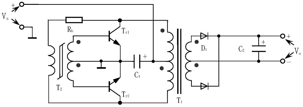
[0073] see Figure 5 , first show the circuit parameters and measured performance of the prior art, Figure 5 The Jingsen circuit is designed as a converter with an input of 48V and an output of 12V / 1A: the resistor R1 is 33K, the resistor Rb is 16K, the capacitor C1 is 0.047uF / 16V, the parameters of the switch tube: both the triode TR1 and TR2 are FZT853, the withstand voltage Only 100V, the measured value is more than 130V, used in the circuit, the test is not a big problem. Capacitor C is a 10uF / 63V electrolytic capacitor, the output uses Figure 6 Diode D21 and D22 both use 2A / 40V Schottky diodes, and output filter capacitor C21 uses 10uF / 25V tantalum capacitors; among them, the magnetic saturation transformer B1 uses Tiantong’s TS7 ring core , the initial magnetic permeability is 7500, the outer diameter is 5.05mm, the inner diameter is 2.3mm, the thickness is 1.6mm, the primary side winding is 49 turns, the secondary side is 4 turns, with a center tap, that is, the bas...

no. 2 example

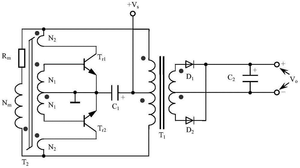
[0107] see Figure 4 ,and Figure 5 The difference is that the capacitors C1 and R1 are connected in parallel. Paragraphs 0029 to 0035 of the Chinese patent 201210174076.7 discuss that this method only affects the startup and does not affect the normal operation. Figure 4 The Jingsen circuit is designed as a converter that inputs 24V and outputs 5V / 0.2A:

[0108] The resistor R1 is 27K, the resistor Rb is 18K, the capacitor C1 is 0.1uF / 10V, the parameters of the switch tube: the triode TR1 and TR2 are both FMMT493, the withstand voltage is only 150V, and the current is 1A. Capacitor C is a chip capacitor of 2.2uF / 10V, the output adopts Figure 6 The full-wave rectification circuit, the diodes D1 and D2 both use 1A / 40V Schottky diodes, and the output filter capacitor C2 uses a 2.2uF / 10V chip capacitor; among them, the ring core made of P46 made by Yuefeng Company is selected. The initial magnetic permeability is 3300, the outer diameter is 5.05mm, the inner diameter is 2.3m...

no. 3 example

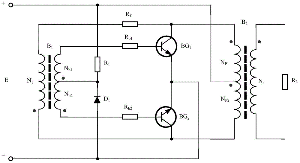
[0119] see Figure 12 ,and Figure 5 The difference is that a resonant capacitor Cd is connected in parallel with both ends of the primary winding of the drive transformer B1, Figure 12 The Jingsen circuit is designed as a converter with an input of 48V and an output of 12V / 1A: the resistor R1 is 33K, the resistor Rb is 16K, the capacitor C1 is 0.047uF / 16V, the parameters of the switch tube: both the triode TR1 and TR2 are FZT853, the withstand voltage Only 100V, the measured value is more than 130V, used in the circuit, the test is not a big problem. Capacitor C is a 10uF / 63V electrolytic capacitor, the output uses Figure 6 In the full-wave rectification circuit, the diodes D1 and D2 both use 2A / 40V Schottky diodes, and the output filter capacitor C2 uses 10uF / 25V tantalum capacitors; among them,

[0120] The magnetic saturation transformer B1 adopts the P47 annular magnetic core made by Yuefeng Company, with a magnetic permeability of 3000, an outer diameter of 5.05mm, ...


PUM


Abstract

The invention provides a quasi-soft switching method of a Jensen circuit converter. A low-magnetic conductivity magnet is adopted by a driver transformer, the impedance of two terminal networks for feedback is increased, the number of turns of the primary winding of the driver transformer is adjusted so that the peak-peak value of the AC working voltage at the two ends of the primary winding of the driver transformer can be greater than four times of the working voltage of the Jensen circuit, in other words, the original magnetic saturation working square wave of the primary winding of the driver transformer is changed into resonant approximate sine wave, meanwhile, a triode for push pull has an all-off working interval within which a no-load main transformer is excited by use of the electric energy of the driver transformer through the two terminal networks to realize zero-voltage on of the triode for push pull, and therefore, the soft switching at the on moment is realized, and zero-current shutdown cannot be realized at the off moment; the method is capable of improving the conversion efficiency, and after the working frequency rises, the efficiency is still maintained at a relatively high level.

Description

technical field [0001] The invention relates to a self-excited push-pull converter, in particular to a soft-switching method and circuit of a Jingsen circuit converter. Background technique [0002] The existing self-excited push-pull converters are generally divided into two categories: Royer circuit and Weller circuit. [0003] The Royer circuit comes from the self-excited oscillating push-pull transistor single-transformer DC converter invented by G.H.Royer in 1955, usually referred to as the Royer circuit, which is also the beginning of the realization of high-frequency conversion control circuits; Jen Sen, most of the literature translated as "Jingsen") invented the self-excited push-pull double transformer circuit, which was later called the self-oscillating Jensen circuit and the self-excited push-pull Jensen circuit, and most of the literature was called Jingsen circuit; these two The circuit is called a self-excited push-pull converter by later generations. [000...

Claims


Application Information

Patent Timeline
Patent Type & Authority Patents(China)
IPC IPC(8): H02M3/337
CPCH02M1/083H02M3/337Y02B70/10
Inventor 王保均
Owner MORNSUN GUANGZHOU SCI & TECH
Why Eureka
Try Eureka