Horizontal device and method for friction-stir welding of circular seam of carrier rocket storage tank assembly

A friction stir, launch vehicle technology, applied in auxiliary devices, welding equipment, welding equipment, etc., to achieve high-efficiency welding, small torque, and reliable positioning

Active Publication Date: 2015-03-11
CAPITAL AEROSPACE MACHINERY +2
View PDF5 Cites 16 Cited by
  • Summary
  • Abstract
  • Description
  • Claims
  • Application Information

AI Technical Summary

Problems solved by technology

At present, there is no complete set of friction stir weld

Method used


Image

  • Horizontal device and method for friction-stir welding of circular seam of carrier rocket storage tank assembly
  • Horizontal device and method for friction-stir welding of circular seam of carrier rocket storage tank assembly
  • Horizontal device and method for friction-stir welding of circular seam of carrier rocket storage tank assembly

Examples


Embodiment 1

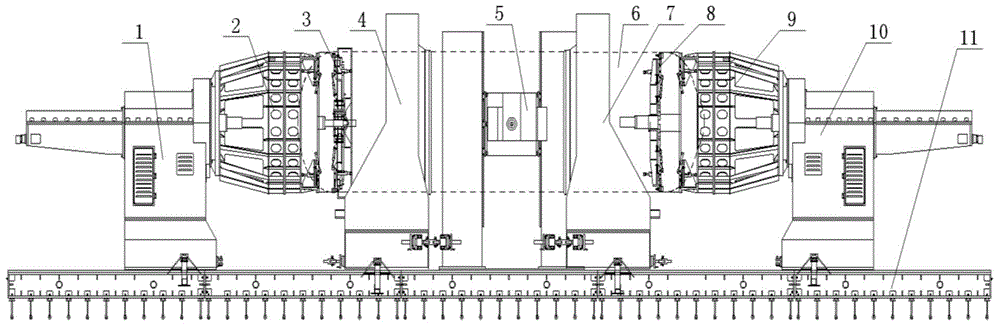
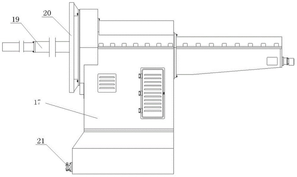
[0027] Such as figure 1 As shown in the present invention, a horizontal device for friction stir welding of a launch vehicle storage tank assembly circular seam, the storage tank 6 is a front short shell, a front bottom, a multi-section barrel section, and a rear The bottom and a rear short shell are welded in sequence. The device includes a bed 11, and the head of the bed 10 and the tail of the bed 1 are arranged at both ends above the bed 11 respectively; Compression mechanism 4 and rear transition ring 2; Inner support mechanism 8, bar system support mechanism 3 are hung on the head of a bed telescopic shaft 19 and the tail of a bed telescopic shaft 25 respectively, and can move horizontally with the telescopic axis.

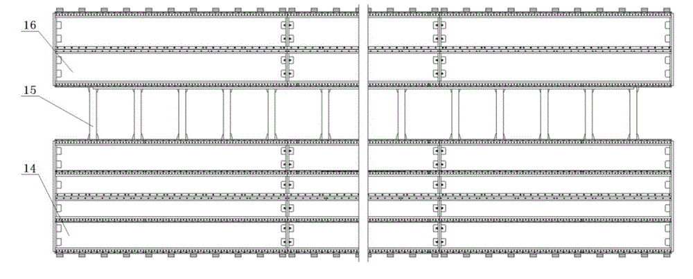
[0028] Such as figure 2 As shown, the bed 11 includes a main bed 14 and an auxiliary bed 16, and the main bed 14 and the auxiliary bed 16 are connected by a number of reinforcing beams 15, which can better eliminate the influence of the stirring friction f...

Embodiment 2

[0035] Adopt the horizontal welding method of the friction stir welding of the circular seam of the general assembly of the launch vehicle storage tank of the horizontal device described in embodiment 1, the described storage tank 6 is composed of 1 front short shell, 1 front bottom, multi-section barrel sections, A rear bottom and a rear short shell are sequentially welded; the welding method includes the following steps:

[0036] (a) Hoist the front short shell and front bottom assembly on the head of the bed 10, connect the front short shell with the front transition ring 9 in quadrants; 2 Connect according to the quadrant; move the right outer positioning and pressing mechanism 7 to the front bottom, position and press the front short shell and the front bottom, move the left outer positioning and pressing mechanism 4 to the first section of the cylinder, position and press Tighten the first barrel section; hoist the inner support mechanism 8 on the telescopic shaft 19 at ...


PUM


Abstract

The invention provides a horizontal device and a method for friction-stir welding of a circular seam of a carrier rocket storage tank assembly. The device comprises a bed body, wherein a bed head and a bed tail are respectively arranged at the two ends above the bed body; a front transition ring, an outer right positioning and compressing mechanism, an outer left positioning and compressing mechanism and a rear transition ring are arranged between the bed head and the bed tail in sequence; an inner supporting mechanism and a rod system supporting mechanism are respectively hung on a bed head telescopic shaft and a bed tail telescopic shaft and can move horizontally along with the telescopic shafts; a stirring host is arranged on the bed body. The method comprises the following steps of welding a front bottom with a first cylinder section, welding a front short shell with the front bottom, welding the rest cylinder sections with the cylinder section, welding the cylinder sections and a rear bottom, and welding a rear short shell and a rear bottom. According to the horizontal device and the method, one-time clamping, in-situ edge milling and welding of the storage tank can be realized; the assembling precision and the welding efficiency are greatly improved; high-precision and high-efficiency welding of a rocket storage tank can be realized; the effect is good.

Description

technical field [0001] The invention relates to the technical field of aerospace equipment welding, in particular to a horizontal device and method for friction stir welding of a carrier rocket tank general assembly circular seam. Background technique [0002] Friction stir welding technology has become a very ideal welding method for aluminum alloy tank welding in the aerospace field due to its many technical advantages such as high joint quality, less defects, and small deformation. The thruster tank is composed of a front short shell, a front bottom, multi-section barrel sections, a rear bottom, and a rear short shell welded in sequence. At present, there is no complete set of friction stir welding equipment for horizontal tank girth seam in my country. Contents of the invention [0003] The object of the present invention is to provide a horizontal device and method for friction stir welding of the circular seam of the general assembly of the launch vehicle tank, whic...

Claims


Application Information

Patent Timeline
IPC IPC(8): B23K20/12B23K37/04B23K20/24
CPCB23K20/122B23K20/126
Inventor 王国庆邱龙高培涛赵衍华王德志孔德跃刘亮
Owner CAPITAL AEROSPACE MACHINERY
Why Eureka
Try Eureka