
Device and method of melting polysilicon powder by electron beam

An electron beam smelting, polysilicon technology, applied in chemical instruments and methods, silicon compounds, inorganic chemistry, etc., can solve the problems of long smelting time and increased energy consumption of electron beam smelting, shorten the smelting time, save manpower and material resources, reduce The effect of energy consumption

Inactive Publication Date: 2015-03-11
DALIAN UNIV OF TECH
View PDF3 Cites 3 Cited by
  • Summary
  • Abstract
  • Description
  • Claims
  • Application Information

AI Technical Summary

Problems solved by technology

[0003] However, due to the surface heating characteristics of the electron beam, that is, although the heating local temperature can reach more than 3000°C, the penetration zone of the heating melt is only a dozen millimeters, at most tens of millimeters, which will cause the first block to be added. The solid material will fall into the bottom layer of the raw material melt, and the electron beam cannot directly act on the added bulk material, but gradually melts the first added bulk material through the radiant heat of the electron beam heating the upper melt, among which The volatile impurities are also gradually diffused from the bottom layer to the surface layer by diffusion and removed. This process leads to a longer melting time and increases the energy consumption of electron beam melting.

Method used


Image

  • Device and method of melting polysilicon powder by electron beam

Examples


Embodiment 1

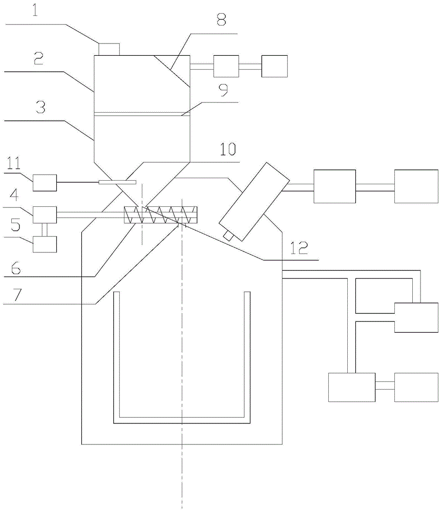
[0026] Such as figure 1 As shown, a device for electron beam smelting polysilicon powder includes a melting chamber, an electron gun and its vacuum system, a melting chamber vacuum system, a crucible and a feeding system, and the feeding system includes a feeding bin 2 and an inlet below it The feeding bin 3, the feeding bin 2 and the feeding bin 3 are isolated by a butterfly valve 9; the bottom of the feeding bin 3 is provided with a feeding port 12 leading into the smelting chamber, and the lower end of the feeding port 12 is connected to a screw feeder 6, and the screw feeder 6 The feeder is connected to the geared motor 4 and the time controller 5, and the speed of the geared motor 4 is controlled by adjusting the time controller 5 to drive the screw feeder 6 to realize feeding at a fixed rate, and the feeding rate can be adjusted. A bulk material opening is provided below the screw feeder, and the diameter of the bulk material opening is 5 mm; the diameter of the cross se...

Embodiment 2

[0035] Such as figure 1As shown, a device for electron beam smelting polysilicon powder includes a melting chamber, an electron gun and its vacuum system, a melting chamber vacuum system, a crucible and a feeding system, and the feeding system includes a feeding bin 2 and an inlet below it The feeding bin 3, the feeding bin 2 and the feeding bin 3 are isolated by a butterfly valve 9; the bottom of the feeding bin 3 is provided with a feeding port 12 leading into the smelting chamber, and the lower end of the feeding port 12 is connected to a screw feeder 6, and the screw feeder 6 The feeder is connected to the geared motor 4 and the time controller 5, and the speed of the geared motor 4 is controlled by adjusting the time controller 5 to drive the screw feeder 6 to realize feeding at a fixed rate, and the feeding rate can be adjusted. A bulk material opening is provided below the screw feeder, and the diameter of the bulk material opening is 20 mm; the diameter of the cross se...


PUM

PropertyMeasurementUnit
Diameteraaaaaaaaaa
Diameteraaaaaaaaaa

Abstract

The invention relates to a device for melting polysilicon powder by an electron beam and a method for utilizing the device to melt the polysilicon powder and belongs to the field of electron beam melting. The device for melting the polysilicon powder by the electron beam comprises a melting chamber, an electronic gun, a vacuum system of the electronic gun, a melting chamber vacuum system, a crucible and a feeding system and is characterized in that the feeding system consists of a feeding cabin and a material inlet cabin arranged below the feeding cabin, the feeding cabin is isolated from the material inlet cabin by virtue of a butterfly valve; a material inlet which is introduced into the melting chamber is formed in the bottom of the material inlet cabin, and the lower end of the material inlet is connected with a screw feeder; a material level sensor is arranged above the material inlet and is connected with an alarm; a feeding hole is formed in one side of the top of the feeding cabin. According to the device and the method disclosed by the invention, with addition of powdery polysilicon, the phosphorous removal efficiency is improved by more than 30 percent, the melting time is shortened by more than 20 percent, and the energy consumption is lowered.

Description

technical field [0001] The invention relates to a device for smelting polysilicon powder with an electron beam and a method for smelting polysilicon by using the device, belonging to the field of electron beam smelting. Background technique [0002] The technology of electron beam smelting to remove volatile impurities in polysilicon, refractory metals and rare metals is relatively mature. The high energy density, high melting temperature and local overheating of electron beams can effectively remove volatile impurities in raw materials. . At present, because the working environment of electron beam smelting technology is a vacuum condition, the addition and replenishment of raw materials is in the form of lumps with a certain particle size. [0003] However, due to the surface heating characteristics of the electron beam, that is, although the heating local temperature can reach more than 3000°C, the penetration zone of the heating melt is only a dozen millimeters, at most...

Claims


Application Information

Patent Timeline
IPC IPC(8): C01B33/037
Inventor 谭毅姜大川石爽王登科
Owner DALIAN UNIV OF TECH
Features
  • Generate Ideas
  • Intellectual Property
  • Life Sciences
  • Materials
  • Tech Scout
  • Unparalleled Data Quality
  • Higher Quality Content
  • 60% Fewer Hallucinations
Learn More