Nozzle throat section water cooling structure

A nozzle and throat technology, applied in the field of hypersonic low-density wind tunnel, can solve the problems of inability to improve the structural strength of the inner wall of the nozzle, messy equipment layout, and water leakage of pipe joints, and achieve good cooling effect, convenient replacement and maintenance, The effect of avoiding water leakage

Inactive Publication Date: 2017-03-01
BEIJING AEROSPACE YISEN WIND TUNNEL ENG TECH
View PDF6 Cites 2 Cited by
  • Summary
  • Abstract
  • Description
  • Claims
  • Application Information

AI Technical Summary

Problems solved by technology

[0004] At present, there is only one hypersonic low-density wind tunnel in China. Its nozzle is a water-cooled nozzle, and its cooling water channel is opened on the inner surface of the semicircular pad. The semicircular pad needs to be processed into a circular pad first. , and then use wire cutting to cut one into two, and process the longitudinal water tank on the inner surface of the circular cushion block. The process is complicated, the processing is difficult, the cost is high, and the structural strength of the inner wall of the nozzle cannot be improved.
Several cooling water inlet and outlet pipes of the nozzle are connected to the upper inlet and outlet of the flange of the outer casing through pipe joints. Since there are many inlets and outlets on the flange, several inlet and outlet pipes are connected, which makes the equipment layout very messy. And when the throat section needs to be replaced, each inlet and outlet pipe joint must be repeatedly assembled and disassembled, which takes a lot of work and effort, and repeated disassembly and assembly of the pipe joint is likely to cause water leakage

Method used


Image

  • Nozzle throat section water cooling structure
  • Nozzle throat section water cooling structure
  • Nozzle throat section water cooling structure

Examples


Embodiment Construction

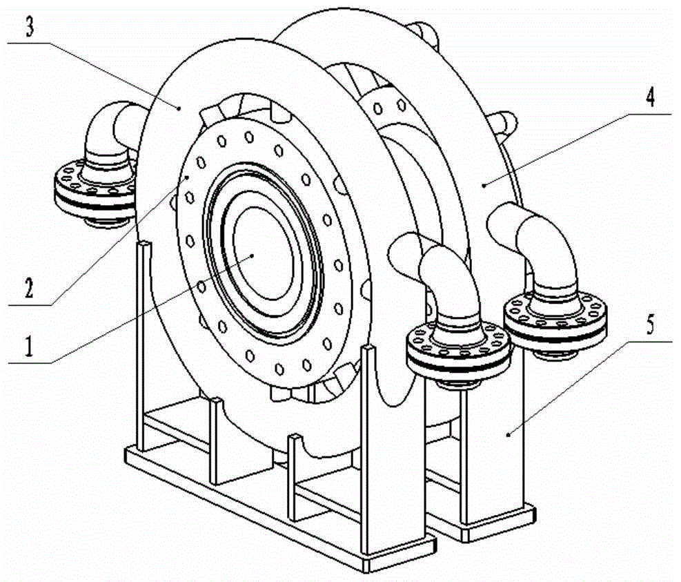
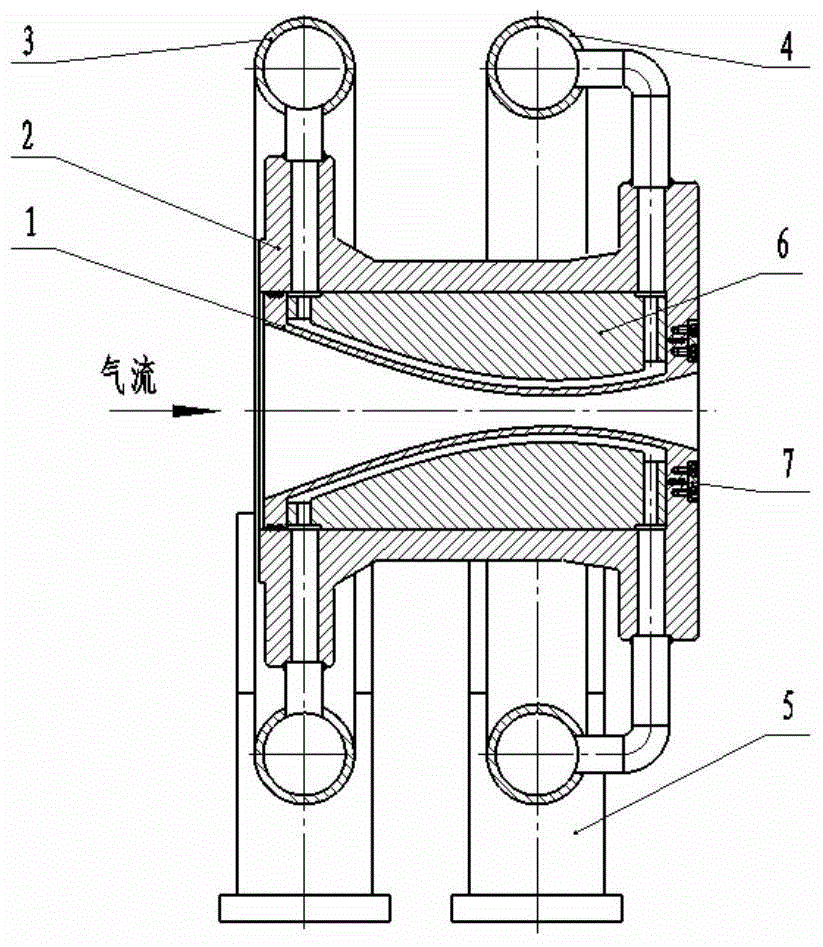
[0017] Such as figure 1 , 2 As shown, the water-cooling structure of the nozzle throat section of the hypersonic low-density wind tunnel includes the inner wall of the nozzle 1, the outer shell 2, the cooling water inlet water collection ring 3, the cooling water outlet water collection ring 4, the small bracket 5, and the clamp block 6, and retaining ring 7 forms. The outer surface of the inner wall 1 of the nozzle is longitudinally grooved to form a cooling water channel; the clamping block 6 is two semicircular bodies matching the shape of the inner wall 1 of the nozzle and the outer shell 2, and the inner surface of the clamping block 6 is a profile curve. The outer surface is a cylindrical surface, and two clamping blocks 6 are combined and installed in the throat section of the nozzle; the rear end of the inner wall 1 of the nozzle along the airflow direction and the outer casing 2 are fixed by a retaining ring 7, and the other end can be properly stretched under high t...


PUM


Abstract

The invention provides a spray pipe throat channel segment water cooling structure comprising a spray pipe internal wall, an external shell, a cooling water inlet water collection ring, a cooling water outlet water collection ring, small supports, a clamping block and a blocking circle. The clamping block is wrapped on the spray pipe internal wall. A cooling water channel is formed between the spray pipe internal wall and the clamping block. The rear end along an airflow direction of the spray pipe internal wall is connected with the external shell via the blocking circle. The cooling water inlet water collection ring and the cooling water outlet water collection ring are annular rings surrounding the external shell and are respectively configured on the front end along the airflow direction of the external shell and circumference of the external side of the rear end. The cooling water inlet water collection ring is connected with the external shell via water inlet pipes which are circumferentially and evenly distributed on the cooling water inlet water collection ring. The cooling water outlet water collection ring is connected with the external shell via water outlet pipes which are circumferentially and evenly distributed on the cooling water outlet water collection ring. The cooling water inlet water collection ring and the cooling water outlet water collection ring are connected with the foundation via the small supports configured below the cooling water inlet water collection ring and the cooling water outlet water collection ring respectively. The spray pipe throat channel segment water cooling structure is great in cooling effect, and the requirement of a hypersonic speed low-density wind tunnel blowing test can be met. Besides, the structure is simple, dismounting is convenient and cost is saved.

Description

technical field [0001] The invention relates to the field of hypersonic low-density wind tunnels, in particular to a water-cooling structure of a nozzle throat section of a hypersonic low-density wind tunnel. Background technique [0002] The low-density wind tunnel is essentially a hypersonic wind tunnel, which has all the characteristics of a blowing-suction wind tunnel, and is an important test equipment for studying the aerodynamic characteristics of rarefied gases. [0003] The nozzle is an important part that accelerates the airflow to the required speed and produces a uniform flow in the test section. It is very important for the design of hypersonic wind tunnel. The heating temperature of the hypersonic low-density wind tunnel heater is very high, which can reach above 1400K, so the heat flux density at the throat of the nozzle is very high, and the throat of the nozzle must be cooled with cooling water. [0004] At present, there is only one hypersonic low-density ...

Claims


Application Information

Patent Timeline
Patent Type & Authority Patents(China)
IPC IPC(8): G01M9/04
Inventor 沈逢京穆东波孙勇堂
Owner BEIJING AEROSPACE YISEN WIND TUNNEL ENG TECH
Why Eureka
Try Eureka