Supercharge Your Innovation With Domain-Expert AI Agents!

A Frequency Selective Surface with Switching Properties and Design Method

A technology of frequency selective surface and switching characteristics, applied in electrical components, circuits, waveguide-type devices, etc., can solve the problems of narrow working frequency band, narrow working bandwidth, complicated design, etc. simple effect

Active Publication Date: 2017-06-09
GUANGDONG MIKWAVE COMM TECH
View PDF9 Cites 0 Cited by
  • Summary
  • Abstract
  • Description
  • Claims
  • Application Information

AI Technical Summary

Problems solved by technology

Its disadvantages are: the working frequency band is narrow (if you want to obtain a wide frequency band, you need to arrange a variety of unit structures with resonance characteristics, and the design is quite complicated), and the metal part is prone to arcing under the irradiation of high-power electromagnetic waves, and the metal part is easy to corrode
[0005] The existing frequency selective surface is to print various metal structures on the dielectric substrate, or periodically arrange the openings on the conductive metal screen. The main working mechanism is electromagnetic resonance, so its working bandwidth is narrow and the design is complicated; while the metal layer It is easy to generate arcs under the irradiation of high-power electromagnetic waves, and the ohmic loss generated by large currents will cause temperature rise; when working with high-frequency electromagnetic waves, its surface wave loss will increase; the metal layer is also easy to corrode in harsh working environments

Method used


Image

  • A Frequency Selective Surface with Switching Properties and Design Method
  • A Frequency Selective Surface with Switching Properties and Design Method
  • A Frequency Selective Surface with Switching Properties and Design Method

Examples


Embodiment 1

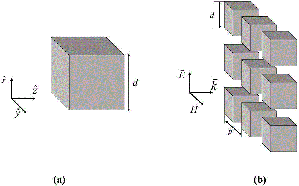
[0033] Such as image 3 As shown, the dielectric column array will produce magnetic dipole and electric dipole resonance under the irradiation of plane electromagnetic waves. It is explained by the theory of artificial electromagnetic (Metamaterial) developed around 2000 that the dielectric column array is equivalent to a single negative (Negative permeability or negative permittivity) Electromagnetic materials, when electromagnetic waves propagate in such materials, their field distribution decays exponentially and cannot propagate, and the displacement current loss in dielectric materials is very low and absorbs very little. So electromagnetic waves are almost totally reflected.

[0034] The dielectric constant (ε) of the dielectric resonator in the current THz and microwave bands r ) Can be very large, ε r Dielectric materials >100 can also be processed, which allows the dielectric column array to be made very thin in the microwave range, which can be used to prepare frequency ...


PUM


Abstract

The invention discloses a frequency selective surface with switching characteristics and a design method. The method is as follows: step 1: according to the requirement of the working frequency band of the frequency selective surface, select a dielectric material with low loss and a suitable dielectric constant to design the shape of the dielectric resonator, Then, observe the electromagnetic wave propagation characteristics of the FSS formed by the dielectric resonator array through the electromagnetic field full-wave simulation software; step 2: invert the equivalent electromagnetic parameters of the frequency selection surface according to the S parameters obtained from the simulation, and judge the magnetic dipole, electric The spectral position of the dipole and four dipole moments; then fine-tune the size of the dielectric column to adjust the dipole resonance position, so that its band-stop frequency band meets the design requirements; Step 3: split all the dielectric columns of the frequency selective surface from the middle into Two layers, simulate and calculate the band-pass characteristics of its working frequency band, and determine the distance between the two layers of dielectric column arrays; Step 4: According to the results obtained in step 3, process and manufacture two layers of the same dielectric column array, and connect them with mechanical devices.

Description

Technical field [0001] The invention relates to an all-medium microwave and millimeter wave frequency selective surface with switching characteristics, which belongs to the field of photoelectric technology. Background technique [0002] The frequency selective surface (ie: Frequency Selective Surface—FSS) is usually a two-dimensional periodic structure with frequency selective characteristics, which is equivalent to a spatial filter, and is widely used in aircraft radomes to reduce the radar cross section (RCS). Communication and electromagnetic protection also play an important role. [0003] The traditional frequency selection surface is generally composed of periodically arranged metal patch units or periodically arranged opening units on a conductive metal screen. This surface structure uses the resonance of the metal structure to achieve total reflection (band stop FSS) or Full transmission (bandpass type FSS) characteristics. Its disadvantages are: the working frequency ba...

Claims


Application Information

Patent Timeline
Patent Type & Authority Patents(China)
IPC IPC(8): H01P1/20H01P11/00
Inventor 王正斌高超薛曼琳陈进昌
Owner GUANGDONG MIKWAVE COMM TECH
Features
  • R&D
  • Intellectual Property
  • Life Sciences
  • Materials
  • Tech Scout
  • Unparalleled Data Quality
  • Higher Quality Content
  • 60% Fewer Hallucinations
Learn More