Lathe turntable with oil collecting function
A functional and lathe technology, applied in the field of lathe turntables, can solve the problems of polluting the working environment, waste debris and oil scattering, etc., and achieve the effects of reducing work intensity, facilitating recycling, and facilitating cleaning
- Summary
- Abstract
- Description
- Claims
- Application Information
AI Technical Summary
Problems solved by technology
Method used
Image

Examples
Embodiment 1
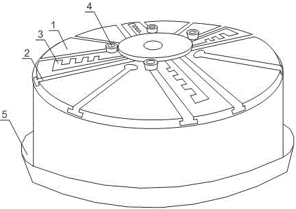
[0020] Such as figure 1 As shown, this embodiment includes a workbench 1 and a rotating shaft. The rotating shaft is placed at the center of the workbench 1. There are multiple sets of combination grooves arranged on the workbench 1. The combination grooves include three T-shaped grooves 2 and toothed grooves arranged in sequence. 3. The direction of the T-shaped groove 2 and the toothed groove 3 coincides with the radial direction of the workbench 1, and also includes a compression bolt 4 slidably arranged on the combined groove, and an oil collection groove 6 is arranged between the bottom of the workbench 1 . The workbench 1 set simply by the traditional milling machine, due to the limitations of its clamping tools, leads to the limited types of workpieces processed by the milling machine. Through the improvement of the traditional workbench 1, the use range of the milling machine can be expanded, and the practicability of the milling machine can be improved. There are mul...
Embodiment 2
[0022] Such as figure 1 As shown, in this embodiment, on the basis of Embodiment 1, the workbench 1 is circular, and the milling machine is divided into a knife-moving type and a heart-moving type. Moving forward, while the tool does not move, the parts are processed through the linear motion or rocking motion of the tool; the machining process of the knife-feeding type: the workpiece is clamped with a simple clamp, and the workpiece is processed by moving the turning tool forward, backward, left, and right; workbench 1 is set as The circular shape can not only meet the requirements of the rotary milling machine, but also meet the standard of the rotary milling machine, which increases the application range of the milling machine.
Embodiment 3
[0024] Such as figure 1 As shown, this embodiment is based on Embodiment 1, and the cross section of the oil collecting groove 6 is an inverted isosceles trapezoid. The isosceles trapezoidal oil collection tank 6 with inverted section can effectively deposit the mixture of waste chips and engine oil, the upper layer is engine oil or other liquid substances, and the lower layer is waste chips; when processing the collected mixture, the upper layer of engine oil is now removed , and then manually collect the waste, which speeds up the collection efficiency.
PUM
 Abstract
Description
Claims
Application Information
 - R&D
- Intellectual Property
- Life Sciences
- Materials
- Tech Scout
- Unparalleled Data Quality
- Higher Quality Content
- 60% Fewer Hallucinations
Browse by: Latest US Patents, China's latest patents, Technical Efficacy Thesaurus, Application Domain, Technology Topic, Popular Technical Reports.
© 2025 PatSnap. All rights reserved.Legal|Privacy policy|Modern Slavery Act Transparency Statement|Sitemap|About US| Contact US: help@patsnap.com