Conductive adhesive material, solar cell module, and manufacturing method for solar cell module

A technology for solar cells and manufacturing methods, applied in the directions of conductive adhesives, adhesives, adhesive types, etc., can solve problems such as breakage and warpage of solar cells, and achieve the effects of good output characteristics and high electrical connection reliability.

Active Publication Date: 2015-03-18
DEXERIALS CORP
7 Cites 3 Cited by

AI-Extracted Technical Summary

Problems solved by technology

However, since soldering is performed at a high temperature of about 300°C, there is a problem...

Method used

From the comparison of Example 1 and Comparative Example 5, it can be seen that by coordinating the SnBi58 solder particles with a melting point of 139° C., compared with the case of coordinating higher solder particles with a melting point, adhesion and connection reliability are all improved .
Wherein, when using conductive adhesive with pasty state, the viscosity of epoxy resin, volatility, curability (pot life) are excellent, can ensure the heat resistance of conductive adhesive and/or long-term Reliability considerations are preferred. Moreover, when using a conductive adhesive as a film-shaped conductive adhesive film, it is preferable to combine an epoxy resin and a film-forming resin. By blending the film-forming resin, the conductive adhesive can be easily molded into a film, and the bonded portion can be protected from heat and/or physical impact. Therefore, by combining an epoxy resin and a film-forming resin, it is possible to combine the heat resistance and long-term reliability of the former with the film-formability and impact absorption of the lat...

Abstract

The invention provides a conductive adhesive material, a solar cell module, and a manufacturing method for a solar cell module. Provided is the conducive adhesive material that enables an electrode of a solar cell unit and a wire to be connected, can be bound at low temperature, achieves highly electrical connection stability and keeps the connection stability for a long period of time. The conducive adhesive material that enables the electrode of the solar cell unit and the wire to be electrically connected is characterized by containing a curing component, a curing agent, conductive particles, a curing accelerator and organic acid, wherein the curing agent contains anhydride, the conductive particles include solder particles and silver-coated copper powder, and the melting point of the solder particles is 80 DEG C to 140 DEG C.

Application Domain

Final product manufactureEpoxy resin adhesives +3

Technology Topic

Organic acidElectricity +8

Image

  • Conductive adhesive material, solar cell module, and manufacturing method for solar cell module
  • Conductive adhesive material, solar cell module, and manufacturing method for solar cell module
  • Conductive adhesive material, solar cell module, and manufacturing method for solar cell module

Examples

  • Experimental program(13)
  • Comparison scheme(3)

Example

[0150]
[0151] First, the first embodiment of the manufacturing method of the solar cell module of the present invention will be exemplified.
[0152] The first embodiment of the manufacturing method of the solar battery module of the present invention is to connect the surface electrode of one solar battery cell and the back electrode of another solar battery cell adjacent to the same solar battery cell through a conductive adhesive and wire A method of manufacturing a solar cell module electrically connected by applying a paste-like conductive adhesive (conductive paste) between the surface electrode and the wiring of the one solar cell and the other solar cell The conductive adhesive is temporarily placed between the back electrode and the wiring, and the conductive adhesive is heated and cured.
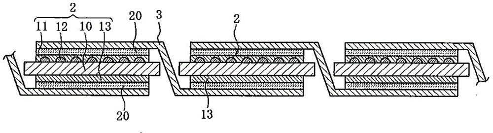
[0153] Specifically, first, Ag paste is applied to the surface of the photoelectric conversion element 10, the finger electrodes 12 and the bus bar electrodes 11 are formed by firing, and the connection portion of the wiring 3 is formed on the back surface by Al screen printing. The Al back electrode 13 is used to produce a solar battery cell.
[0154] Next, a conductive adhesive 20, which is a thermosetting conductive paste, is applied to the bus bar electrode 11 on the surface of the photoelectric conversion element 10 and the Al back electrode 13 on the back, and wiring is arranged on the conductive adhesive 20 3. Use pins for temporary fixation. From the standpoint of preventing deformation and the like, it is preferable not to apply pressure to the solar battery cell as much as possible, and it is preferable to set the pressure applied to the solar battery cell by temporary fixing to 0.1 MPa or less.
[0155] Then, heating by air blowing is performed from the side of the wire 3 to cure the conductive adhesive 20, thereby electrically connecting the wire 3 to the bus bar electrode 11 and the Al back electrode 13. At the time of this connection, the temperature of the air blowing is preferably 200°C or lower, more preferably a relatively low temperature of 140°C to 180°C, and the heating time is preferably set to about 3 seconds to 7 seconds. At this time, for the wiring 3, since the cured component of the conductive adhesive 20 has good adhesiveness with the bus bar electrode 11 formed of Ag paste, it can be mechanically and firmly connected to the bus bar electrode 11. In addition, the wire 3 is electrically connected to the Al back electrode 13.
[0156] The matrix 5 to which the solar battery cells 2 are connected is sandwiched by the plate 6 of sealing adhesive, and the surface cover 7 provided on the light-receiving side and the back plate 8 provided on the back side are laminated together as a protective material, thereby Manufacturing solar cell module 1.

Example

[0157]
[0158] Next, the second embodiment of the manufacturing method of the solar cell module of the present invention will be exemplified.
[0159] In the second embodiment of the method for manufacturing a solar cell module of the present invention, a conductive adhesive film in which the conductive adhesive is a film is applied to the connection between the electrode and the wiring. The second embodiment of the manufacturing method of the solar battery module of the present invention is to connect the surface electrode of one solar battery cell and the back electrode of another solar battery cell adjacent to the same solar battery cell through a conductive adhesive and through wiring The method of manufacturing an electrically connected solar cell module is to temporarily arrange a conductive adhesive film between the surface electrode and the wiring of the one solar cell and between the back electrode and the wiring of the other solar cell, Use a heating press to press from the upper surface of the wire. The conductive adhesive film referred to here is as described above, the curing component, curing agent, conductive particles, curing accelerator, and organic acid are suspended in a solvent, and the resulting suspension is applied to the release substrate It is formed after volatilizing the solvent.
[0160] In the second embodiment, a conductive adhesive film is attached to the bus bar electrode 11 on the surface of the photoelectric conversion element 10 and the Al back electrode 13 on the back surface, and the wiring 3 is arranged on the conductive adhesive film for temporary fixation. The heating press head is heated and pressed from the upper surface of the wire 3 at a predetermined temperature and pressure to cure the conductive adhesive film. During the curing, the temperature of the heating head is preferably 200°C or lower, more preferably 140°C to 190°C; the heating pressing time is preferably 2 seconds to 10 seconds, more preferably 3 seconds to 5 seconds. Thereby, the wiring 3 can be electrically connected to the bus bar electrode 11 and the Al back electrode 13.
[0161] In the above-mentioned first embodiment, instead of applying the conductive adhesive and heating with blast, the steps of applying a conductive adhesive film and heating and pressing with a heating press are carried out as described above. The same process as in the first embodiment becomes the second embodiment described above.

Example

[0162]
[0163] Next, a third embodiment of the manufacturing method of the solar cell module of the present invention will be exemplified.
[0164] In the third embodiment of the manufacturing method of the solar cell module of the present invention, curing of the sealing resin and connection of the electrodes and the wires are performed simultaneously. The third embodiment of the manufacturing method of the solar battery module of the present invention is to connect the surface electrode of one solar battery cell and the back surface of another solar battery cell adjacent to the same solar battery cell through a conductive adhesive and through wiring. A method for manufacturing a solar cell module with electrically connected electrodes, applying the paste-like conductive adhesive (conductive paste) to connect the surface electrode and wiring of the one solar cell and the back electrode of the other solar cell Temporarily fix it with the wiring. Laminate a sealing material and a protective substrate on the upper and lower surfaces of the solar cell unit. Use a laminating device to laminate and press the upper surface of the protective substrate to cure the sealing material and simultaneously make The surface electrode is connected to the wiring, and the back electrode is connected to the wiring.
[0165] First, a laminating device that simultaneously performs curing of the sealing resin and connection of electrodes and wires will be described.
[0166] image 3 It is a cross-sectional view showing the configuration of an example of a vacuum laminator used in an embodiment of the method for manufacturing a solar cell module of the present invention.
[0167] in image 3 Among them, the vacuum laminator 30 is composed of an upper unit 31 and a lower unit 32. These units are separably integrated by sealing members 33 such as O-rings. The upper unit 31 is provided with a flexible plate 34 such as silicone rubber, and the vacuum laminator 30 is divided into a first chamber 35 and a second chamber 36 by the flexible plate 34.
[0168] In addition, in each of the upper unit 31 and the lower unit 32, the internal pressure of each chamber can be adjusted independently, that is, the pressure can be reduced and pressurized by the vacuum pump and/or the compressor, and the atmosphere can be opened. Pipe 37, pipe 38. The pipe 37 is branched by the switching valve 39 into two directions, the pipe 37a and the pipe 37b, and the pipe 38 is branched by the switching valve 40 into two directions, the pipe 38a and the pipe 38b. In addition, a heating table 41 is provided in the lower unit 32.
[0169] Next, a specific connection method using this vacuum laminator 30 will be described. First, the upper unit 31 and the lower unit 32 are separated, and the following laminate is placed on the table 41. The laminate is laminated with a sealing material and a protective base material (surface cover 7. The backplane 8) is made. It should be noted that the temperature when the wire is temporarily fixed to the solar battery cell may be lower than the melting point of the solder particles of the conductive paste.
[0170] Then, the upper unit 31 and the lower unit 32 are detachably integrated through the sealing member 33, and then a vacuum pump is connected to the pipe 37a and the pipe 38a, respectively, so that the first chamber 35 and the second chamber 36 are high vacuum. When maintaining a high vacuum in the second chamber 36, the switching valve 39 is switched to introduce the air from the pipe 37b into the first chamber 35. As a result, the flexible plate 34 expands to the second chamber 36, and as a result, the laminate is heated by the stage 41 while being pressed by the flexible plate 34.
[0171] After the thermocompression bonding, the switching valve 40 is switched so that the atmosphere is introduced into the second chamber 36 from the pipe 38b. Thereby, the flexible plate 34 is pushed back toward the first chamber 35, and finally the internal pressures of the first chamber 35 and the second chamber 36 become the same.
[0172] Finally, the upper unit 31 and the lower unit 32 are separated, and the solar cell module subjected to thermal compression bonding is taken out from the table 41. As a result, the curing of the sealing resin and the connection of the electrodes and the wires can be performed simultaneously.
[0173] Here, since a strong metal bond can be formed between the wire and the electrode and high connection reliability can be obtained, it is preferable that the thermocompression bonding temperature in the laminating device be higher than the melting point of the solder particles of the conductive paste. On the other hand, from the viewpoint of preventing damage to the solar cell, it is preferably set to a predetermined temperature or lower. Specifically, the thermocompression bonding temperature is preferably 200°C, and more preferably 140°C to 160°C. Here, by using a conductive adhesive whose curing start temperature of the curing material is equal to or higher than the melting point of the solder particles, the curing agent and the epoxy compound can be cured after the curing agent has a sufficient flux function. In this case, if the difference between the curing start temperature of the curing agent and the melting point of the solder particles is 15° C. or less, it is preferable to use a conductive adhesive, since a sufficient flux effect can be obtained and connection reliability can be improved.

PUM

PropertyMeasurementUnit
The average particle size30.0µm
Melting point131.0 ~ 134.5°C

Description & Claims & Application Information

We can also present the details of the Description, Claims and Application information to help users get a comprehensive understanding of the technical details of the patent, such as background art, summary of invention, brief description of drawings, description of embodiments, and other original content. On the other hand, users can also determine the specific scope of protection of the technology through the list of claims; as well as understand the changes in the life cycle of the technology with the presentation of the patent timeline. Login to view more.

Similar technology patents

Speed changing constant frequency double feeding wind power generator exciting frequency variator based on super conductive magnetic storage energy

InactiveCN1901360AExcellent output characteristicsReduce harmonic content
Owner:HUAZHONG UNIV OF SCI & TECH

Positive electrode for secondary cell, method for manufacturing positive electrode secondary cell, and secondary cell

ActiveCN106463730AExcellent flexibility and adhesionExcellent output characteristics
Owner:ZEON CORP

Classification and recommendation of technical efficacy words

  • Excellent output characteristics

Speed changing constant frequency double feeding wind power generator exciting frequency variator based on super conductive magnetic storage energy

InactiveCN1901360AExcellent output characteristicsReduce harmonic content
Owner:HUAZHONG UNIV OF SCI & TECH

Positive electrode for secondary cell, method for manufacturing positive electrode secondary cell, and secondary cell

ActiveCN106463730AExcellent flexibility and adhesionExcellent output characteristics
Owner:ZEON CORP
Why Eureka
Try Eureka