
Method for reducing stickiness in manufacturing process of micro-electro-mechanic-system microphone

A micro-electro-mechanical system and manufacturing process technology, applied in the field of micro-electro-mechanical system microphone manufacturing process and semiconductor manufacturing process, can solve the problems affecting the yield rate of microphone products, and achieve the effect of improving the yield rate and reducing the occurrence of stickiness

Active Publication Date: 2015-03-18
CSMC TECH FAB2 CO LTD
View PDF4 Cites 7 Cited by
  • Summary
  • Abstract
  • Description
  • Claims
  • Application Information

AI Technical Summary

Problems solved by technology

When drying in the prior art, due to the influence of the surface tension of the liquid, the diaphragm of the MEMS microphone will be driven to move toward the substrate, and finally the diaphragm and the substrate will stick together, resulting in stickiness, such as Figure 4 As shown, and this phenomenon is irreversible, that is to say, it is impossible to separate the diaphragm and substrate of the sticky microphone, which will affect the yield of the microphone product.

Method used


Image

  • Method for reducing stickiness in manufacturing process of micro-electro-mechanic-system microphone
  • Method for reducing stickiness in manufacturing process of micro-electro-mechanic-system microphone
  • Method for reducing stickiness in manufacturing process of micro-electro-mechanic-system microphone

Examples


Embodiment Construction

[0027] The present invention will be further described in detail below in conjunction with the accompanying drawings and embodiments. It should be understood that the specific embodiments described here are only used to explain the present invention, but not to limit the present invention. In addition, it should be noted that, for the convenience of description, only parts related to the present invention are shown in the drawings but not all content.

[0028] exist Figure 5 A first embodiment of the invention is shown in .

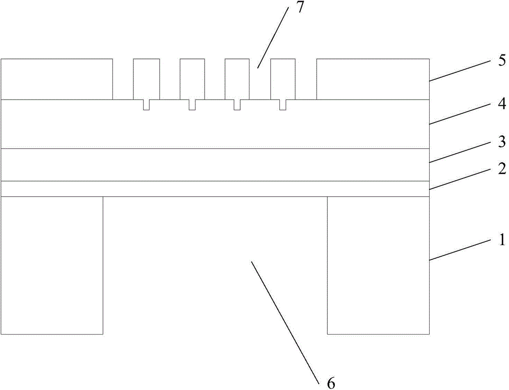
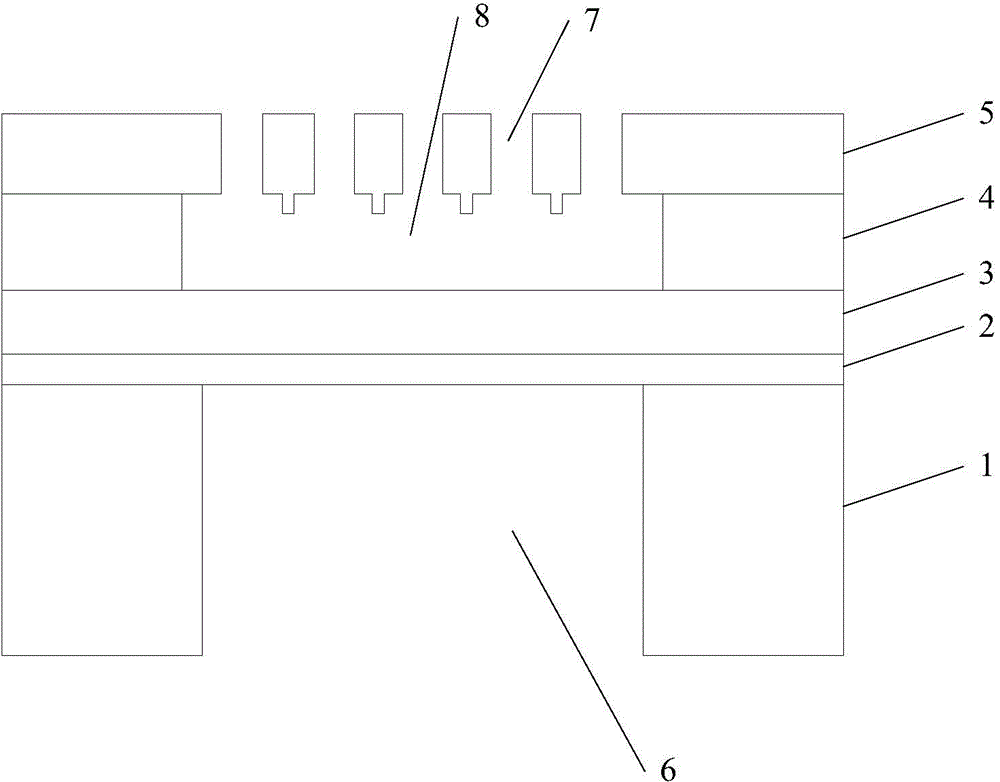
[0029] Figure 5 It is the implementation process 500 of the method for reducing the stickiness generated in the manufacturing process of MEMS microphones in the first embodiment of the present invention. figure 1 is a schematic cross-sectional view of the general structure of a MEMS microphone before media release. Such as figure 1 As shown, the MEMS microphone includes: a silicon substrate (SI) 1 with an acoustic back cavity 6, an oxide film (OX) ...


PUM


Abstract

The invention discloses a method for reducing stickiness in a manufacturing process of a micro-electro-mechanic-system microphone. The micro-electro-mechanic-system microphone includes a silicon substrate with an acoustic rear cavity, an oxide film on the silicon substrate, a first polycrystalline silicon layer on the oxide film, a silicon dioxide layer on the first polycrystalline silicon layer, and a second polycrystalline silicon layer which is on the silicon dioxide layer and provided with sound holes. The method includes the following steps: removing the silicon dioxide layer so as to form an acoustic front cavity; cleaning the micro-electro-mechanic-system microphone; immersing the micro-electro-mechanic-system microphone in a low-surface-tension liquid; and drying the micro-electro-mechanic-system microphone so as to enable the low-surface-tension liquid in the acoustic front cavity to volatilize and at the same time, and using sound wave vibration to enable a vibrating diaphragm of the micro-electro-mechanic-system microphone to vibrate so as to reduce generation of stickiness. During drying of the micro-electro-mechanic-system microphone, sound wave vibration is used so enable the vibrating diaphragm of the micro-electro-mechanic-system microphone to vibrate so that a probability that a stickiness phenomenon happens is reduced and the yield of the micro-electro-mechanic-system microphone is improved.

Description

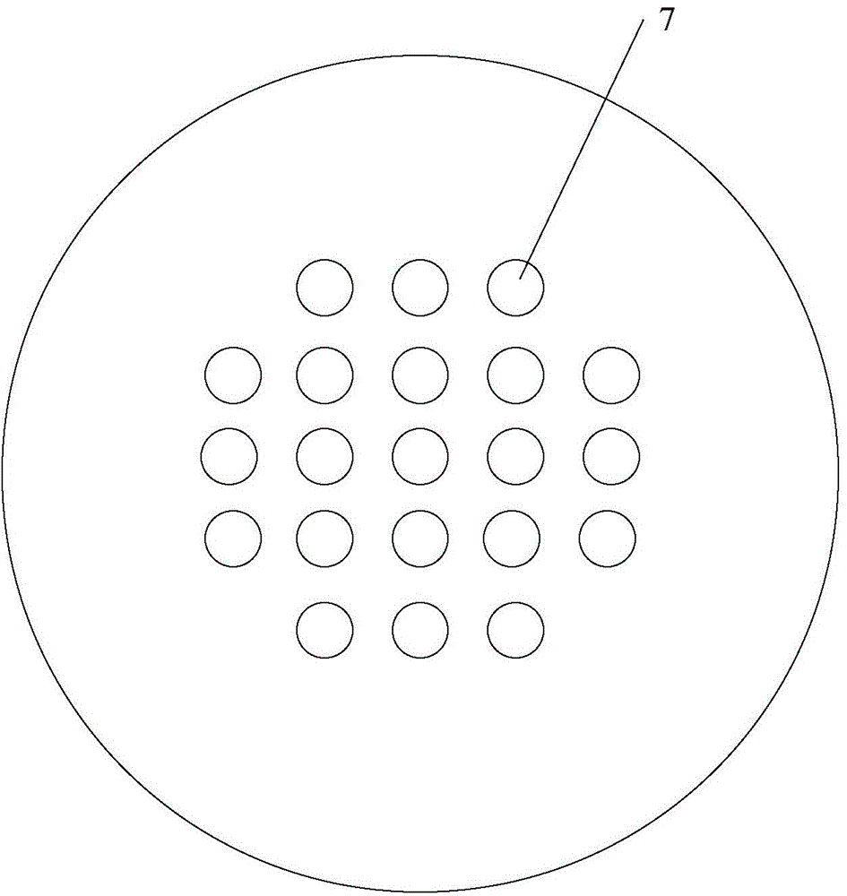
technical field [0001] The invention relates to the field of semiconductor manufacturing technology, in particular to the field of micro-electro-mechanical system microphone manufacturing technology, and in particular to a method for reducing stickiness generated during the manufacturing process of micro-electro-mechanical system microphones. Background technique [0002] In the micro-electro-mechanical system (Micro-Electro-Mechanic System, MEMS) process, for microphone products, it is necessary to release the medium between the diaphragm and the substrate. [0003] figure 1 A schematic cross-sectional view of the MEMS microphone before media release is shown. Such as figure 1 As shown, the MEMS microphone before dielectric release includes a silicon substrate 1 with an acoustic back cavity 6, an oxide film 2 on the silicon substrate, a first polysilicon layer (Poly1 ) 3. A silicon dioxide layer 4 on the first polysilicon layer, a second polysilicon layer (Poly2) 5 with ...

Claims


Application Information

Patent Timeline
IPC IPC(8): H04R31/00
Inventor 孙其梁
Owner CSMC TECH FAB2 CO LTD
Learn More