Flue gas desulfurization device

A desulfurization device and flue gas technology, applied in the separation of dispersed particles, chemical instruments and methods, separation methods, etc., can solve the problems of disturbed circulating water, high desulfurization tower, difficult layout, etc., to increase the contact surface and contact time, prolong the Contact time, effect of improving desulfurization efficiency

Inactive Publication Date: 2015-03-25
GUANGXI NANNING HUAGUO ENVIRONMENT SCI & TECH
View PDF6 Cites 6 Cited by
  • Summary
  • Abstract
  • Description
  • Claims
  • Application Information

AI Technical Summary

Problems solved by technology

Because of the large solution of sodium hydroxide in water, this method will not cause supersaturated crystallization, cause fouling and blockage of pipelines, and reduce investment and operation costs. It is widely used in desulfurization process, but the existing desulfurization tower is relatively High, difficult to arrange, cumbersome to clean, poor desulfurization effect, and when the regeneration tank is cleaning the sediment, it will disturb the circulating water, and the sediment at the bottom of the tank will be stirred up, causing the circulating water to become turbid, resulting in a change in the effect of the regeneration tank sedimentation and desulfurization agent regeneration Difference

Method used


Image

  • Flue gas desulfurization device

Examples


Embodiment Construction

[0025] The present invention will be further described in detail below in conjunction with the accompanying drawings, so that those skilled in the art can implement it with reference to the description.

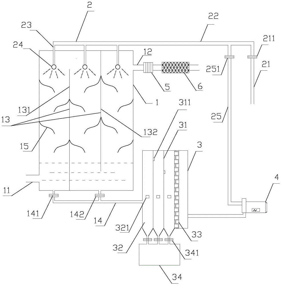
[0026] like figure 1 As shown, the present invention provides a flue gas desulfurization device, comprising:

[0027] The box body 1 is provided with an air inlet pipe 11 on the lower left side, and an air outlet pipe 12 on the upper right side. The inside of the box body is provided with a partition 13, and from left to right are the first lower partition 131 and the first upper partition. Partition plate 132, wherein the first lower partition plate 131 is vertically connected with the bottom of the box body 1 to divide it into a first filter tank and a second filter tank, and the bottoms of the first filter tank and the second filter tank are respectively provided with connecting rows The liquid discharge branch pipe of the liquid pipe 14 is provided with a flow regulating...


PUM


Abstract

The invention discloses a flue gas desulfurization device. The flue gas desulfurization device comprises a box body, a spraying mechanism, a regenerating tank and a circulating pump, wherein the box body is provided with a gas inlet pipe and a gas outlet pipe; partition plates which are arranged in an up-down staggered manner are arranged in the box body to divide the bottom of the box body into a first filter tank and a second filter tank; the bottoms of the first filter tank and the second filter tank are respectively connected with a liquid discharging branch pipe of a liquid discharging pipe; the spraying mechanism comprises a first liquid inlet pipe, a second liquid inlet pipe, and a first liquid inlet branch pipe, wherein a first desulfurizing agent is introduced into the first liquid inlet pipe; the first liquid inlet branch pipe is connected with the second liquid inlet pipe; the first liquid inlet pipe is connected with the second liquid inlet pipe; the first liquid inlet pipe and a spraying head are arranged at the top of the box body; a first liquid inlet which is connected with the liquid discharging pipe is formed in one side surface of the regenerating tank; a liquid outlet is formed in the side surface opposite to the first liquid inlet; a second desulfurizing agent is arranged at the bottom of the regenerating tank; the circulating pump is connected with the liquid outlet of the regenerating tank and the second liquid inlet pipe. The flue gas desulfurization device disclosed by the invention has a good desulfurization effect; the feculence cleaning operation of the regenerating tank is simple, and the desulfurizing agent in the regenerating tank is not required to be discharged, so that raw materials are saved.

Description

technical field [0001] The invention relates to the technical field of air pollution prevention and control, in particular to a flue gas desulfurization device. Background technique [0002] my country is a big coal-burning country. Coal-fired accounts for 75% of primary energy, and 90% of sulfur dioxide emissions come from coal combustion. Among them, sulfur dioxide emissions cause acid rain, which seriously damages the ecological environment and affects people's health. [0003] At present, flue gas desulfurization technology is the main way to solve the pollution of flue gas emissions. Among them, the double-alkali flue gas desulfurization technology uses sodium-based desulfurization agent to absorb sulfur dioxide, and then discharges the desulfurization product into the regeneration tank for reduction and regeneration with calcium hydroxide, while the regenerated Sodium-based desulfurizer can be recycled. Because of the large solution of sodium hydroxide in water, this ...

Claims


Application Information

Patent Timeline
Patent Type & Authority Applications(China)
IPC IPC(8): B01D53/78B01D53/50B01D53/96
Inventor 覃江浩
Owner GUANGXI NANNING HUAGUO ENVIRONMENT SCI & TECH
Why Eureka
Try Eureka