CNC engraving and milling machine for precision machining

A technology of precision machining, engraving and milling machine, applied in the direction of metal processing mechanical parts, metal processing equipment, milling machine, etc., can solve the problems of low machining accuracy and product forming efficiency, weak bearing capacity of engraving and milling machine, etc., to improve the smooth operation, Good balance and low friction loss

Active Publication Date: 2015-03-25
SUZHOU EASSON OPTOELECTRONICS
View PDF7 Cites 8 Cited by
  • Summary
  • Abstract
  • Description
  • Claims
  • Application Information

AI Technical Summary

Problems solved by technology

[0003] Existing engraving and milling machines have weak bearing capacity, low machining accuracy and low product forming efficiency. How to design an engraving and milling machine with strong bearing capacity, high precision, high speed, high machining accuracy and high product forming rate has become an effort for those skilled in the art. direction

Method used


Image

  • CNC engraving and milling machine for precision machining
  • CNC engraving and milling machine for precision machining
  • CNC engraving and milling machine for precision machining

Examples


Embodiment

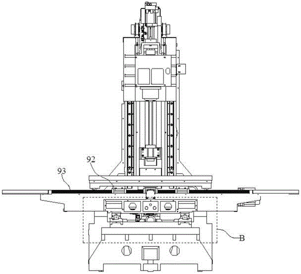
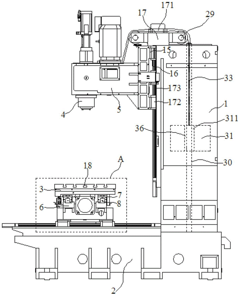
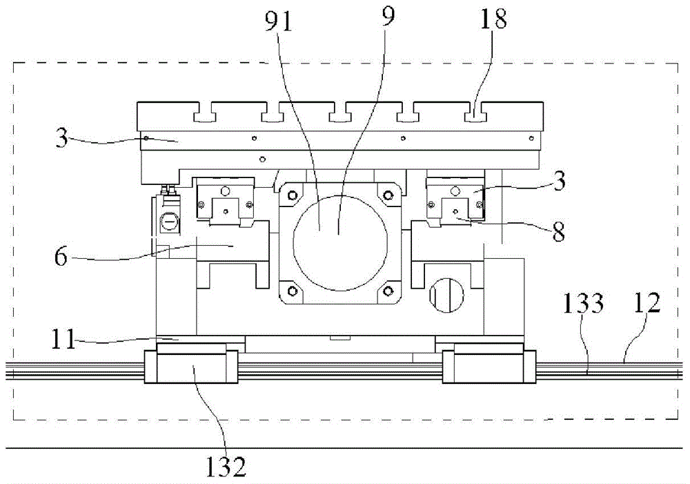
[0032] Embodiment: A CNC engraving and milling machine for precision machining, including a column 1, a base 2, a worktable 3, a machine head 5 with a cutter 4, a first steel ring sleeve 19, a second steel steel ring sleeve 20, and a third The steel ring sleeve 26, the fourth steel ring sleeve 27 and the support plate 6 between the base 2 and the workbench 3, the column 1 is fixed on the upper surface of the base 2, and the machine head 5 is located on the upper side of the column 1 And above the workbench 3;

[0033] The column 1 includes a column 101, a first support leg 102 and a second support leg 103 respectively fixed on both sides of the lower end surface of the column 101, the first support leg 102 and the second support leg 103 are respectively fixed to the base 2 On both sides of the upper surface, a hollow area is formed between the first supporting leg 102, the second supporting leg 103, the base 2 and the column 101;

[0034] At least two x-direction sliders 7 are fix...


PUM


Abstract

The invention discloses a CNC engraving and milling machine for precision machining, which comprises a machine head, a first steel ring sleeve, a second steel ring sleeve, a third steel ring sleeve and a fourth steel ring sleeve, wherein the machine head is provided with a cutter; the front end part of an x-direction lead screw positioned in an x-direction main bearing mechanism is embedded in the first steel ring sleeve, an x-direction motor output shaft is embedded in the second steel ring sleeve, two ends of a first cushion spring are respectively fixedly connected with the end surfaces of the first steel ring sleeve and the second steel ring sleeve, a pulley block is arranged on the upper end surface of a stand column, a straight bar is fixedly arranged in the cavity of the stand column, a counter balance the center of which is provided with a through hole is positioned in the cavity of the stand column, the straight bar is embedded in the through hole of the counter balance, two ends of the counter balance are respectively connected to one ends of a first steel wire rope and a second steel wire rope, the other ends of the first steel wire rope and the second steel wire rope are respectively connected to two ends of the upper end surface of the machine head through the pulley block. According to the CNC engraving and milling machine for the precision machining, the damage and the deformation caused by the eccentricity and errors of the motor output shaft and the lead screw can be prevented, the running is smooth, the balance property is good, the CNC engraving and milling machine for the precision machining has a self-adjustment function and the high efficiency and the precision can be further guaranteed.

Description

Technical field [0001] The invention relates to a numerical control engraving and milling machine, in particular to a numerical control engraving and milling machine for precision processing. Background technique [0002] Engraving and milling machine is a high-precision and efficient automatic cutting machine tool. The prior art engraving and milling machine tools generally include a base, X-axis motion mechanism, Y-axis motion mechanism, Z-axis motion mechanism, column, beam, worktable, and electric spindle And electrical control device. It can process planes, grooves, various curved surfaces, gears, etc. A milling machine is a machine tool that uses a milling cutter to mill a workpiece. In addition to milling planes, grooves, gear teeth, threads, and spline shafts, milling machines can also process more complex profiles. The efficiency is higher than that of planers. It is the most widely used type of machine tool in machinery manufacturing and repair factories. [0003] Exis...

Claims


Application Information

Patent Timeline
IPC IPC(8): B23C1/06B23C9/00B23Q1/01B23Q11/00B23Q5/40
CPCB23C1/06B23Q1/01B23Q1/015B23Q1/58B23Q1/621B23Q1/72B23Q5/40B23Q5/402B23Q11/00B23Q11/0017
Inventor 陆庆年姚先凯
Owner SUZHOU EASSON OPTOELECTRONICS
Why Eureka
Try Eureka