Automatic welding workpiece machine and dip soldering method

A dip soldering and automatic technology, applied in the direction of welding equipment, auxiliary devices, printed circuits, etc., can solve the second soldering operation of PCB boards that cannot be cut, and complete preheating, flux spraying, soldering, Problems such as foot cutting operation and low integration level of automatic tin dipping machine are achieved, and the effect of compact structure, high integration level and improved production efficiency is achieved.

Inactive Publication Date: 2015-03-25
乐清市浙佳电子科技有限公司
View PDF10 Cites 19 Cited by
  • Summary
  • Abstract
  • Description
  • Claims
  • Application Information

AI Technical Summary

Problems solved by technology

[0007] For this reason, the technical problem to be solved by the present invention is that the integration degree of the existing automatic tin dipping machine is not high, and it is impossible to simultaneously complete preheating, flux spraying, soldering, and foot cutting operations on one piece of equipment, and it is also impossible to complete the operation on one piece of equipment

Method used


Image

  • Automatic welding workpiece machine and dip soldering method
  • Automatic welding workpiece machine and dip soldering method
  • Automatic welding workpiece machine and dip soldering method

Examples


Embodiment 1

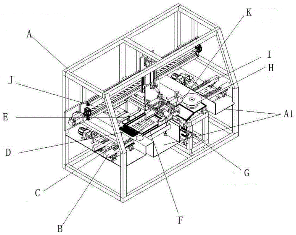
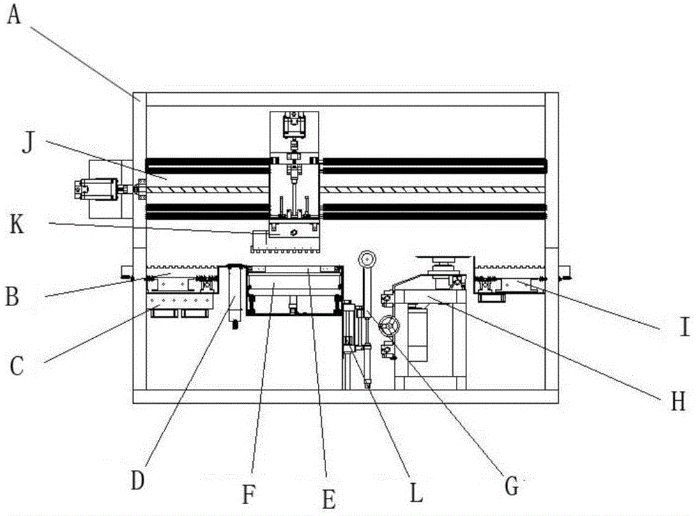
[0057] Such as figure 1 , 2 As shown, the present embodiment provides an automatic dip soldering machine, including: a support frame A with a running plane of the PCB board 10 inside, a board feeding mechanism B for sending the PCB board 10 into the running plane, and a board feeding mechanism B for sending the PCB board 10 into the running plane. 10 Preheating preheating mechanism C, spraying mechanism D for spraying flux to the PCB 10, tin furnace mechanism F for containing solder liquid, used for inserting the preheated PCB 10 into the tin furnace at a certain angle Mechanism F for clamping and dipping soldering mechanism K for soldering, used for scraping off the tin oxide surface layer in tin furnace mechanism F before PCB board 10 is soldered, and scraping mechanism E for making PCB board 10 leave the running plane after soldering Board ejection mechanism I, and the transmission mechanism J that can do reciprocating motion above the described operating plane and is used...

Embodiment 2

[0109] This embodiment provides a dip soldering method, using the dip soldering machine as described in Embodiment 1, comprising the following steps:

[0110] S1: The PCB board is transported to the running plane through the board feeding mechanism B, the PCB board is clamped by the clamping and dipping mechanism K, and the clamping and dipping mechanism K is driven by the transmission mechanism J to transport the PCB board to the working place where the preheating mechanism C is located. bit;

[0111] S2: Preheat the PCB board through the preheating mechanism C;

[0112] S3: Transport the PCB board to the station where the spray mechanism D is located through the transmission mechanism J, and spray flux through the spray mechanism D;

[0113] S4: Transport the PCB board to the station where the tin furnace mechanism F is located through the transmission mechanism J, start the tin scraping mechanism E to scrape off the tin oxide surface layer in the tin furnace mechanism F, s...


PUM


Abstract

The invention relates to an automatic welding workpiece machine. The automatic welding workpiece machine integrates a plate feeding mechanism, a preheating mechanism, a spraying mechanism, a solder machine mechanism, a tin scrapping mechanism, a conveying mechanism, a clamping dip soldering mechanism, a footing cutting mechanism, a slag blocking mechanism and a plate discharging mechanism, so that the automatic welding workpiece machine can accomplish a series operations of preheating, soldering flux spraying, tin soldering and foot cutting simultaneously, and conveys cut feet to the position of the preheating mechanism again through the conveying mechanism and to pass through the preheating mechanism, the spraying mechanism and the solder machine mechanism again, and performs a tin soldering operation again to realize secondary tin soldering on a PCB (printed circuit board). By being provided with the foot cutting mechanism, the problem that tin fluid is polluted because the feet cut material drops into a solder machine of the solder machine mechanism when the mechanisms are distributed in compact space and the foot cutting mechanism performs foot cutting on the PCB is solved. In addition, the invention further provides a dip soldering method utilizing the automatic welding workpiece machine.

Description

technical field [0001] The invention relates to an automatic dip soldering machine and a dip soldering method, belonging to the technical field of dip soldering. background technology [0002] In the assembly and production process of electronic products, it is usually necessary to mount the electronic components on the PCB (printed circuit board), and then fix the electronic components on the PCB by welding. At present, the commonly used soldering methods mainly include dip soldering, wave soldering, reflow soldering, etc. For PCB boards that use through-hole insertion, dip soldering is still the main method. Dip soldering is a method of dipping the PCB board with electronic components into the molten tin furnace to complete the welding of many solder joints at one time. [0003] The operation process of dip soldering is as follows: 1. Put tin into the tin furnace and heat the tin furnace to melt the tin; 2. Apply flux on the printed circuit board and component pins, usual...

Claims


Application Information

Patent Timeline
IPC IPC(8): B23K3/00B23K3/08B23K1/08H05K3/34
CPCB23K1/08B23K3/00B23K3/08B23K2101/42H05K3/34
Inventor 余青生郑志杨陈俏函
Owner 乐清市浙佳电子科技有限公司
Why Eureka
Try Eureka