Steel pipe end alignment system and method

A technology of steel pipe and roller table, which is applied in the direction of clamping, supporting, positioning devices, etc., can solve the problems that the center of rotation cannot be coaxial, the roundness of steel pipes cannot meet the requirements, and the precision of steel pipes is low.

Active Publication Date: 2015-03-25
TIANSHUI METALFORMING MACHINE TOOL GROUP
View PDF7 Cites 16 Cited by
  • Summary
  • Abstract
  • Description
  • Claims
  • Application Information

AI Technical Summary

Problems solved by technology

Some production lines process the end of the steel pipe on a horizontal lathe, but due to the large length of the steel pipe (10 meters to 12 meters) and the low precision of the steel pipe, the steel pipe must be rotated on the lathe and the axis of the steel pipe and the rotation It is difficult to have the same center; so steel pipes are generally used to fix, and the end of the steel pipe is processed by the cutter head of the milling and boring machine tool. The following problems, when the steel pipe is fixed, the center of the end of the steel pipe and the center of rotation of the cutter head cannot be coaxial (tolerance: ф0.3mm), and the roundness of the steel pipe cannot reach the required value (0.3mm), resulting in milling and boring The qualification rate of the end of the steel pipe processed by the cutter head of the machine tool is low, which cannot meet the process requirements
At present, there is no system that makes the end of the steel pipe processed by the cutter head of the milling and boring machine meet the process requirements and has a high pass rate

Method used


Image

  • Steel pipe end alignment system and method
  • Steel pipe end alignment system and method
  • Steel pipe end alignment system and method

Examples


Embodiment Construction

[0035] The present invention will be further described below in conjunction with accompanying drawing.

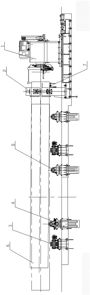
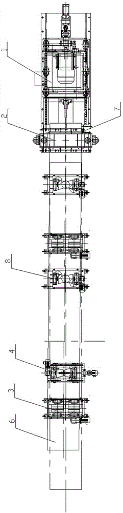
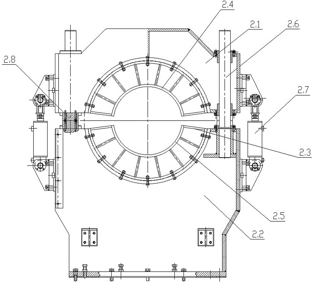
[0036] Such as figure 1 or figure 2 As shown, the present invention includes a clamping device 2 installed in the axial direction of the steel pipe at the working end of the milling and boring machine tool 1, a lifting and conveying roller table 8, a rotating device 3 and a traverse lifting and conveying roller table 4; the clamping device 2 is close to the milling and boring The machine tool 1 is set to clamp and ensure the roundness of the steel pipe end; the traverse lift conveying roller table 4 is set away from the milling and boring machine tool to transport and adjust the position of the steel pipe end at the other end of the steel pipe, that is, when the steel pipe end is in the state to be processed, clamp The device is located at the end of the steel pipe to be processed, and the traversing lifting conveying roller table is located at the other end of the steel ...


PUM


Abstract

The invention belongs to the technical field of steel pipe end machining and particularly relates to a system used for clamping and aligning the pipe end of a long steel pipe before the pipe end of the long steel pipe is milled and bored. The steel pipe end alignment system comprises a clamping device mounted in front of a machine tool, lifting and conveying roller ways, rotating devices, a transverse movement lifting and conveying roller way and detection devices. The steel pipe clamping device is arranged close to the machine tool and used for clamping the pipe end of the steel pipe and guaranteeing the roundness of the pipe end of the steel pipe. The transverse movement lifting and conveying roller way is arranged far from the machine tool and used for conveying the steel pipe and adjusting the position of the other end of the steel pipe, so that the center of the clamped end of the steel pipe is coaxial with the rotation center of a cutter head. The lifting and conveying roller ways and the rotating devices are alternately mounted in the axial direction of the steel pipe. The detection devices are mounted in the middle and on the lower portion of the end, close to the machine tool, of the clamping device respectively, one detection device is used for detecting a side mother line of the steel pipe, and the other detection device is used for detecting a lower mother line of the steel pipe. The steel pipe end alignment system is low in improvement cost; after the steel pipe is aligned by the steel pipe end alignment system, the percent of pass of the end, machined by the cutter head of the milling and boring machine tool, of the steel pipe is high, and the production efficiency is improved.

Description

technical field [0001] The invention belongs to the technical field of steel pipe end processing, and in particular relates to a system and method for clamping and aligning a pipe end before processing a large-length steel pipe end by a milling and boring method. Background technique [0002] In order to adapt to the rapid development of the chemical industry, the production lines of composite steel pipes with carbon steel pipes on the outside and stainless steel pipes on the inside have been built one after another in China. In the production line of the composite pipe, the end of the steel pipe needs to be processed twice such as boring the inner hole, digging the inner hole, digging the groove on the end face, and chamfering the flat end. Some production lines process the end of the steel pipe on a horizontal lathe, but due to the large length of the steel pipe (10 meters to 12 meters) and the low precision of the steel pipe, the steel pipe must be rotated on the lath...

Claims


Application Information

Patent Timeline
Patent Type & Authority Applications(China)
IPC IPC(8): B23Q7/05B23Q7/14B23Q17/22B23Q3/08
CPCB23B25/06B23Q15/22
Inventor 仝江涛杜海波郑志敏张品政王亚利
Owner TIANSHUI METALFORMING MACHINE TOOL GROUP
Why Eureka
Try Eureka