
High-speed robot for production assembly line system

A production line and robot technology, applied in the field of robots, can solve problems such as the need to improve production efficiency

Active Publication Date: 2015-03-25
东莞市智赢智能装备有限公司
View PDF6 Cites 12 Cited by
  • Summary
  • Abstract
  • Description
  • Claims
  • Application Information

AI Technical Summary

Problems solved by technology

However, the existing assembly line still stays at the combination of man and machine, and can only automate the delivery of accessories and other products, while the assembly, picking, and selection of accessories and other products still require manual operations, and its production efficiency is still low. needs improvement

Method used


Image

  • High-speed robot for production assembly line system
  • High-speed robot for production assembly line system
  • High-speed robot for production assembly line system

Examples


Embodiment 1

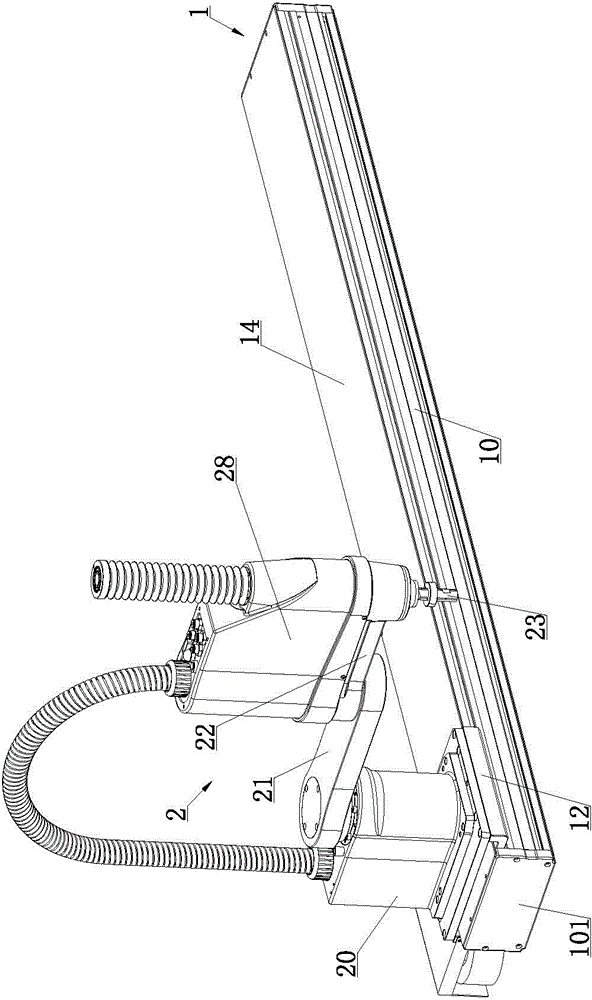
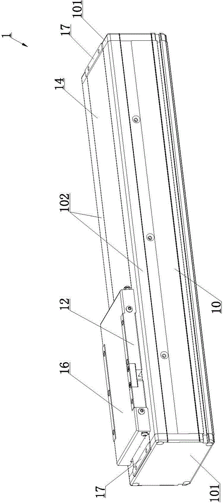
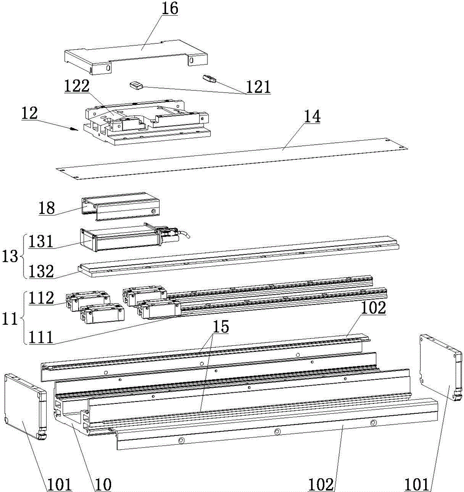
[0042] Such as Figure 1 to Figure 8 As shown, the high-speed robot of the production line system of the present invention includes a single-axis manipulator 1. The single-axis manipulator 1 includes a base 10, a linear slide 11, and a work slide 12. The end of the base 10 is provided with an end cover 101, and the base 10 A side cover 102 is provided on the side, the guide rails 111 of the linear slide rail 11 are fixedly installed on both sides of the base 10, the work slide 12 is connected with the slider 121 of the linear slide 11, and the base 10 is provided with a work slide for driving the work slide 12 moving linear motor 13, a four-axis manipulator 2 is arranged above the work slide 12, the four-axis manipulator 2 includes a base 10, a first cantilever 21, a second cantilever 22, and a screw rod 23, the base 10 and the work slide 12 is fixedly connected, the base 10 is equipped with a first rotation driving device 24, the first end of the first cantilever 21 is located ...

Embodiment 2

[0058] The difference between this embodiment and the first embodiment is that the reducer 251 is a harmonic reducer; the harmonic reducer has high load carrying capacity, large transmission ratio, small size, light weight, high transmission efficiency and long life. The advantages of smooth transmission, no impact, no noise, and high motion accuracy; ensuring the first rotation driving device 24 to control the rotation of the first cantilever 21 and the second rotation driving device 25 to control the rotation of the second cantilever 22 better.

[0059] The rest of this embodiment is the same as the first embodiment, and the unexplained features in this embodiment adopt the explanation of the first embodiment, and will not be repeated here.

[0060] In summary, it can be seen that the present invention has the above-mentioned excellent characteristics, so that it can improve the efficiency and practicability that is not available in the prior art in use, and become a product of gr...


PUM


Abstract

The invention relates to the field of robots, in particular to a high-speed robot for a production assembly line system. The high-speed robot comprises a single-axis mechanical hand, wherein the single-axis mechanical hand comprises a work sliding table and a linear motor for driving the work sliding table to move linearly, the work sliding table is connected with a four-axis mechanical hand, and the four-axis mechanical hand comprises a lead screw and a driving device for driving the lead screw to do four-freedom-degree motion. When the robot is applied to the flow production line, a clamp can be installed on the lead screw, and the four-axis mechanical hand controls the lead screw to do four-freedom-degree motion and can freely control an accessory clamped by the clamp to be assembled, put, taken and the like; the single-axis mechanical hand drives the whole four-axis mechanical hand to move linearly, the linear motor is used as the driving device for the single-axis mechanical hand and can efficiently and accurately control the work sliding table to move, then the work sliding table drives the whole four-axis mechanical hand to move, and therefore the automatic work of the whole flow production line is achieved.

Description

technical field [0001] The invention relates to the technical field of robots, in particular to a high-speed robot of a production assembly line system. Background technique [0002] The assembly line, also known as the assembly line, is an industrial production method, which means that each production unit only focuses on processing a certain segment of work to improve work efficiency and output; according to the transportation method of the assembly line, it can be roughly divided into: belt assembly line, plate There are seven types of assembly lines: chain line, double-speed chain, plug-in line, mesh belt line, suspension line and drum line. It generally includes traction parts, load bearing components, driving devices, tensioning devices, redirecting devices and supporting parts. The assembly line has high scalability, and can design the conveying volume, conveying speed, assembly station, and auxiliary parts (including quick connectors, fans, lamps, sockets, process ...

Claims


Application Information

Patent Timeline
IPC IPC(8): B25J9/12B25J9/08B23P21/00
Inventor 刘阳升
Owner 东莞市智赢智能装备有限公司
Learn More