

Up-flow electro-catalytic reactor
An electrocatalysis and reactor technology, applied in the field of up-flow electrocatalytic reactors, can solve problems such as lack of unified evaluation standards and specifications, and achieve the effects of preventing energy loss, saving costs, and avoiding back-mixing
- Summary
- Abstract
- Description
- Claims
- Application Information
AI Technical Summary
Problems solved by technology
Method used
Image

Examples
Embodiment 1
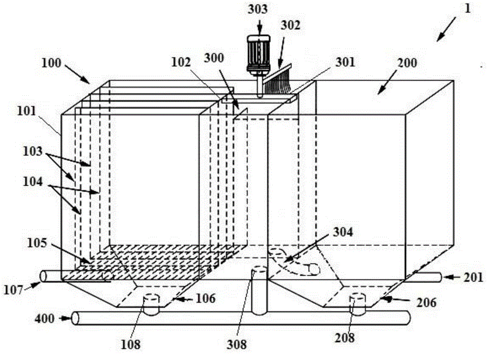
[0028] Such as figure 1As shown, the upflow electrocatalytic reactor 1 of this embodiment is divided into a reaction zone 100 , a skimming zone 300 and a second static sedimentation tank 200 by a reactor shell 101 and a plurality of partitions ( 102 , 103 ).
[0029] Specifically, in the above-mentioned front reaction zone 100, there are: a plurality of anode form stable titanium plates 103 and cathode stainless steel plates 104 arranged in parallel for electrocatalytic operation; The diversion grid 105 vertically arranged on the plate 104; the skip-shaped water collection bucket 106 arranged at the bottom of the diversion grid 105; the water inlet pipe 107 connected to the side of the skip-shaped water collection bucket 106 for the upward flow electrocatalytic reaction Sewage flows into device 1.
[0030] The diversion grid 105 is a stainless steel mesh connected by latitude and longitude lines, and the mesh area is 2×2cm 2 , the warp is parallel to the anode shape-stable t...
Embodiment 2
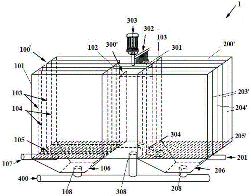
[0040] Such as figure 2 As shown, the upflow electrocatalytic reactor 1 of this embodiment is divided into a front reaction zone 100', a skimming zone 300' and a rear reaction zone 200' by a reactor shell 101 and a plurality of partitions (102, 103).
[0041] In this embodiment, the structures of the pre-reaction zone 100' and the skimming zone 300' are the same as those of the reaction zone 100 and the skimming zone 300 in Embodiment 1, respectively, so the detailed structure thereof is omitted.
[0042] The rear reaction zone 200' is provided with: a plurality of anode shape stable titanium plates 203 and cathode stainless steel plates 204 arranged in parallel for electrocatalytic operation; diversion grid 205; a skip-shaped water collection bucket 206 arranged at the lower part of the diversion grid 205;
[0043] After the electrocatalytic reaction in the front reaction zone 100' and the skimming treatment in the skimming zone 300', the water flows into the rear reaction ...
PUM
| Property | Measurement | Unit |
|---|---|---|
| Length | aaaaa | aaaaa |
Abstract
Description
Claims
Application Information