

Ultralow-loss microwave dielectric ceramic Li3V2B3O11 and preparation method thereof
A microwave dielectric ceramic and ultra-low technology, applied in the field of dielectric ceramic materials, can solve the problems of restricting the development of microwave dielectric ceramics and devices, inability to practical application requirements, and excessive temperature coefficient, and meet the requirements of low temperature co-firing technology and Technical requirements, large application value, and small temperature coefficient of microwave multilayer devices
Active Publication Date: 2015-03-25
GUANGXI NEW FUTURE INFORMATION IND
View PDF2 Cites 1 Cited by
- Summary
- Abstract
- Description
- Claims
- Application Information
AI Technical Summary
Problems solved by technology
[0008] Due to the three performance indicators of microwave dielectric ceramics (ε r with Q f and τ ? ) is a mutually restrictive relationship (see literature: The restrictive relationship between the dielectric properties of microwave dielectric ceramic materials, Zhu Jianhua, Liang Fei, Wang Xiaohong, Lu Wenzhong, Electronic Components and Materials, Issue 3, March 2005), satisfying three There are very few single-phase microwave dielectric ceramics with individual performance requirements, mainly because their resonant frequency temperature coefficient is usually too large or the quality factor is too low to meet the practical application requirements.
At present, most of the research on microwave dielectric ceramics is a summary of experience obtained through a large number of experiments, but there is no complete theory to explain the relationship between microstructure and dielectric properties. Predict the microwave dielectric properties such as resonant frequency temperature coefficient and quality factor, explore and develop near-zero resonant frequency temperature coefficient (-10 ppm / ℃≤τ ? ≤+10 ppm / ℃) and a series of different dielectric constants with high quality factors microwave dielectric ceramics is a difficult problem that those skilled in the art have been eager to solve but have always been difficult to achieve, which largely limits the use of microwave dielectric ceramics and device development
Method used
View moreImage
Smart ImageViewing Examples

Examples
Embodiment
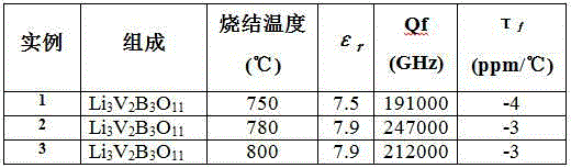
[0017] Table 1 shows three specific examples of different sintering temperatures constituting the present invention and their microwave dielectric properties. The preparation method is as above, and the microwave dielectric performance is evaluated by the cylindrical dielectric resonator method.
[0018] The ceramics can be widely used in the manufacture of microwave devices such as various dielectric substrates, resonators and filters, and can meet the technical needs of mobile communication and satellite communication systems.
[0019] Table 1:
[0020]
Login to View More PUM
 Abstract
The invention discloses temperature-stable type ultralow-loss microwave dielectric ceramic Li3V2B3O11 and a preparation method thereof. The preparation method comprises steps as follows: (1), raw material powder of Li2CO3, V2O5 and H3BO3 with the purity of higher than 99.9% in percentage by weight is weighed and proportioned according to composition of Li3V2B3O11; (2), the raw material powder of the step (1) is subjected to wet type ball milling and mixing for 12 h, the ball milling medium adopts absolute ethyl alcohol, and the raw material powder is dried and pre-sintered in the air atmosphere at the temperature of 700 DEG C for 6 h; and (3), after a binding agent is added to the powder prepared in the step (2) and granulation is performed, the powder is subjected to compression forming and sintered in the air atmosphere at the temperature of 750-800 DEG C for 4 h finally, the binding agent adopts a polyvinyl alcohol solution with the mass concentration of 5%, and the adding amount of polyvinyl alcohol accounts for 3% of the total mass of the powder. The prepared ceramic is sintered well, the dielectric constant reaches 7.5-7.9, the qualify factor (Qf) value is up to 191,000-247,000 GHz, the temperature coefficient of resonance frequency is small, and the prepared ceramic has great industrial application value.
Description
technical field [0001] The invention relates to a dielectric ceramic material, in particular to a dielectric ceramic material for manufacturing microwave components such as ceramic substrates, resonators and filters used in microwave frequencies and a preparation method thereof. Background technique [0002] Microwave dielectric ceramics refer to ceramics that are used as dielectric materials in circuits in the microwave frequency band (mainly UHF and SHF bands) and perform one or more functions. They are widely used as resonators, filters, and dielectric substrates in modern communications. Components such as chips and dielectric waveguide circuits are the key basic materials of modern communication technology. They have been used in portable mobile phones, car phones, cordless phones, TV satellite receivers and military radars. They are used in modern communication tools. It is playing an increasingly important role in the process of miniaturization and integration. [00...
Claims
Login to View More Application Information
Patent Timeline
 IPC IPC(8): C04B35/495C04B35/58C04B35/622
Inventor方维双李纯纯苏和平
OwnerGUANGXI NEW FUTURE INFORMATION IND