
Liquid level monitoring device of infrared storage battery

A technology of liquid level monitoring and battery, applied in the direction of buoy liquid level indicator, etc., can solve the problems of energy consumption crisis and great influence on battery electrical performance.

Inactive Publication Date: 2015-03-25
林州市顺丰电动车业有限公司
View PDF4 Cites 5 Cited by
  • Summary
  • Abstract
  • Description
  • Claims
  • Application Information

AI Technical Summary

Problems solved by technology

[0002] The rapid development of the automobile industry has brought about a serious energy consumption crisis. In order to cope with and solve this problem and realize the renewable and recycling of energy, the industry will focus on electric vehicles in the future. In terms of energy supply for electric vehicles, although there are Fuel cells in the future and current lithium batteries are promising in the future, but in today's applications, lead-acid batteries are still the mainstream. Due to their superior cost and good charge and discharge performance, they are still the most widely used in electric vehicles. , The work of lead-acid batteries is realized by the reversible reaction between the electrolyte and the plate. The quality of the electrolyte has a great influence on the electrical performance of the battery. Especially when the electrolyte is lacking, it needs to be replenished in time to ensure the battery is in normal condition. Usually, the method of detecting the electrolyte is manually and visually identified. This method is obviously no longer suitable for the application of high-power batteries and electric vehicles. In electric vehicles, especially lead-acid batteries for electric vehicles, a more advanced method is needed. For convenient and simple battery liquid level monitoring device

Method used


Image

  • Liquid level monitoring device of infrared storage battery
  • Liquid level monitoring device of infrared storage battery
  • Liquid level monitoring device of infrared storage battery

Examples


Embodiment Construction

[0010] In order to better understand and implement the technical solutions of the present invention, some implementation examples of the present invention are provided here. These implementation examples are for better explaining the technical solutions of the present invention, and do not constitute any form of limitation to the present invention.

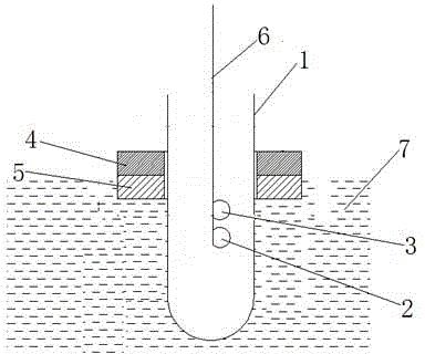
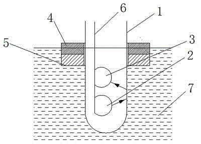
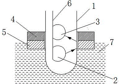
[0011] As shown in the accompanying drawings, the infrared battery liquid level monitoring device is set in the lead-acid battery, and a light-transmitting tube is set in the lead-acid battery electrolyte. The position of the infrared receiving tube is fixed, and the light-transmitting tube is used as a guide post to be provided with an annular float. The annular float is an infrared light-reflecting body with a certain thickness. Under the action, the peripheral guide post of the light-transmitting tube in the center of the annular float moves up and down, and the infrared receiving tube and the infrared emitting tube are provided...


PUM


Abstract

The invention discloses a liquid level monitoring device of an infrared storage battery and belongs to the field of storage batteries for a power vehicle. The liquid level monitoring device is arranged in a lead-acid storage battery, a light transmitting tube is arranged in the electrolyte of the lead-acid storage battery, an infrared transmitting tube and an infrared receiving tube are arranged in the light transmitting tube, the infrared transmitting tube and the infrared receiving tube are fixed, an annular floater is arranged by using the light transmitting tube as a guide column, the annular floater is an anti-infrared light body with a certain thickness, and the annular floater floats on the water level of the electrolyte and moves up and down along the light transmitting tube at the center of the annular floater and serving as the guide column under the action of gravity and buoyancy force. By the liquid level monitoring device, the electric properties of the battery is guaranteed favorably, and the service life of the battery is prolonged.

Description

technical field [0001] The invention relates to an infrared monitoring device, in particular to an infrared storage battery liquid level monitoring device, which belongs to the field of storage batteries for power vehicles. Background technique [0002] The rapid development of the automobile industry has brought about a serious energy consumption crisis. In order to cope with and solve this problem and realize the renewable and recycling of energy, the industry will focus on electric vehicles in the future. In terms of energy supply for electric vehicles, although there are Fuel cells in the future and current lithium batteries are promising in the future, but in today's applications, lead-acid batteries are still the mainstream. Due to their superior cost and good charge and discharge performance, they are still widely used in electric vehicles. , The work of lead-acid batteries is realized by the reversible reaction between the electrolyte and the plate. The quality of th...

Claims


Application Information

Patent Timeline
IPC IPC(8): G01F23/64G01F23/76
Inventor 郭志勇李岳山
Owner 林州市顺丰电动车业有限公司
Learn More