Optical fiber pressure sensing measurement method and device
A technology for sensing measurement and pressure, which is applied in the direction of measuring devices, fluid pressure measurement using optical methods, and rapid measurement changes, and can solve problems such as high cost, complex structure, and low sensitivity
- Summary
- Abstract
- Description
- Claims
- Application Information
AI Technical Summary
Problems solved by technology
Method used
Image

Examples
Embodiment 1
[0067] Relevant description of the present invention:
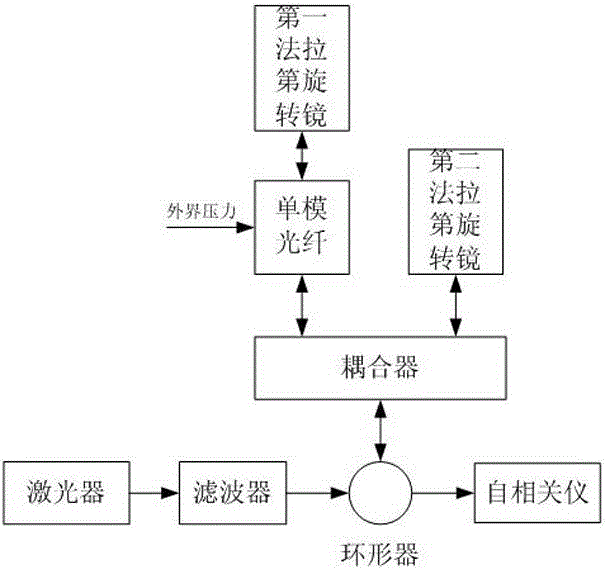
[0068] 1. The optical signal device of the measuring path includes a single-mode optical fiber and the first Faraday rotating mirror,
[0069] Among them, the single-mode optical fiber is used to transmit the optical signal of the measurement path to the first Faraday rotating mirror; at the same time, output the laser signal reflected back by the first Faraday rotating mirror;
[0070] The first Faraday rotating mirror: it is used to receive the same polarization state of the measurement path and the reference path, to ensure the autocorrelation of the two paths of signals, and to reflect the optical signal of the measurement path to the coupler through a single-mode fiber.
[0071] 2. The reference path optical signal device is the second Faraday rotating mirror, which is used to make the measurement path and the reference path have the same polarization state, ensure the autocorrelation of the two paths of signals, and...
Embodiment 1
[0080] Embodiment one: 1. A kind of optical fiber pressure sensing measurement method comprises:
[0081] Step 1: Pulse laser output laser beam;
[0082] Step 2: The output beam of the laser is divided into two optical signals after passing through the filter, circulator and coupler, one of which is the measurement optical signal, and the other information is the reference optical signal;
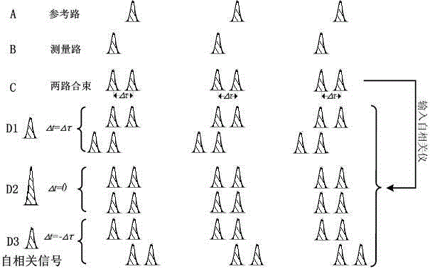
[0083] Step 3: The optical signal of the measurement path is transmitted by the first Faraday rotating mirror after passing through the single-mode fiber; at the same time, the optical signal of the reference path is reflected by the second Faraday rotating mirror, and the optical signal of the measuring path and the optical signal of the reference path are converted into a composite signal through a coupler ;
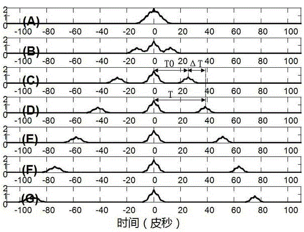
[0084] Step 4: When the single-mode optical fiber is in the zero-pressure state, the composite signal is output to the autocorrelator through the circulator, and the relative delay t...
Embodiment 2
[0099] Embodiment 2: A kind of optical fiber pressure sensing measuring device comprises:
[0100] Pulse laser: used to output laser beam;
[0101] Filter: used to ensure that the measurement path and the reference path have the same spectral components, thereby generating an autocorrelation signal;
[0102] Circulator: used to ensure the correct direction of the optical path;
[0103] Coupler: It is used to divide the laser beam input by the pulse laser into 2 paths and receive 2 paths of reflected signals, so that the light intensity of the two paths can be 1:1 as much as possible when combining the beams after reflection;
[0104] Single-mode optical fiber: used to feel the external pressure, the external pressure causes its refractive index to change, resulting in a change in the delay of the two signals, which is reflected in the change in the distance between the autocorrelation peaks;
[0105] Faraday rotating mirror: used to make the measurement path and the referenc...
PUM
 Abstract
Description
Claims
Application Information
 - R&D
- Intellectual Property
- Life Sciences
- Materials
- Tech Scout
- Unparalleled Data Quality
- Higher Quality Content
- 60% Fewer Hallucinations
Browse by: Latest US Patents, China's latest patents, Technical Efficacy Thesaurus, Application Domain, Technology Topic, Popular Technical Reports.
© 2025 PatSnap. All rights reserved.Legal|Privacy policy|Modern Slavery Act Transparency Statement|Sitemap|About US| Contact US: help@patsnap.com