Thermal desorption device

A thermal desorption and desorber technology, applied in measuring devices, instruments, scientific instruments, etc., can solve the problems of inconvenient use, inability to distill, reduce sample recovery rate and desorption repeatability, etc., and achieve easy fixation and temperature control. The effect of small error, improved sensitivity and accuracy

Active Publication Date: 2015-03-25
DALIAN INST OF CHEM PHYSICS CHINESE ACAD OF SCI
View PDF6 Cites 16 Cited by
  • Summary
  • Abstract
  • Description
  • Claims
  • Application Information

AI Technical Summary

Problems solved by technology

In this patented design, there is a cold zone between the outlet of the inner liner tube and the area A of the sample transfer tube, and the area B between the sample transfer tube and the chromatographic injector, so that the thermally desorbed high-boiling components are in A and B Carryover in both zones reduces sample recovery and desorption repeatability, and components with boiling

Method used


Image

  • Thermal desorption device
  • Thermal desorption device
  • Thermal desorption device

Examples


Example Embodiment

[0032] Example 1

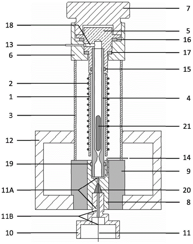
[0033] like figure 1 As shown, a thermal desorption device consists of a heating tube 1, a heating wire 2, an outer sleeve 3, an inner lining tube 4, an inner lining tube pressure head 5, a desorber upper cover 6, an inner lining tube pressure cap 7, Liner base 8, liner base heat insulation ring 9, sample transfer tube fastening pressure cap 10, sample transfer tube 11, desorber base 12, desorption purge gas path 13, desorption split gas path 14, and temperature control elements , which is characterized by:

[0034] The heating tube 1, the outer sleeve 3 and the inner lining tube 4 are all hollow cylindrical structures with openings at the upper and lower ends, and are arranged coaxially; the outer wall of the heating tube 1 is wound with a heating wire 2, and is provided with a thermocouple , the thermocouple and the heating wire 2 are connected with a temperature controller through a wire; the heating tube 1 is placed inside the outer sleeve 3, the outer...

Example Embodiment

[0054] Example 5

[0055] The solid phase microextraction rod was thermally desorbed using the thermal desorption device described in Example 1. Helium was used as the desorption purge gas, the flow rate was adjusted to 3 mL / min, the desorption split gas path was opened, and the split ratio was adjusted to 5:1. The solid phase microextraction rod is coated with polydimethylsiloxane with a film thickness of 70 μm. After extracting the organochlorine pesticides in 20 mL of milk for 30 minutes, it is placed in a lined tube, and a thermal desorption device is inserted for heating. desorption. The desorption conditions were: desorption from 40°C to 300°C within 1.5 minutes for 5 minutes. Gas chromatography was detected by electron capture detector (ECD), and the detection limit was 0.2ng / L.


PUM


Abstract

The invention relates to the technical field of sample detection and discloses a thermal desorption device combined with a gas chromatograph. The thermal desorption device is mainly used for thermal desorption of a solid phase micro-extraction rod, a solid phase micro-extraction stirring bar, a cluster capillary solid-phase micro-extraction pipe and a filling adsorption column and realizes fast desorption of a trace quantity of an adsorbed and enriched ingredient. The thermal desorption device comprises a heating pipe, a lining pipe, a seal ring, a lining pipe pressure cap, a lining pipe base, a lining pipe base heat-insulation ring, a desorption device pedestal, a sample transmission pipe, a desorption purge gas circuit, a desorption shunting gas circuit, a heating wire and a temperature control element. A sample ingredient is subjected to thermal desorption in the lining pipe, and the sample transmission pipe is heated by the heating pipe and thermal conduction of an upper cap of a gas chromatogram sample injector and is subjected to heat insulation by the lining pipe base heat-insulation ring. When a desorption temperature is 300 DEG C, the thermal desorption device has a desorption residual rate less than 0.1% of the ingredient at a boiling point less than 430 DEG C. The thermal desorption device has the advantages of no cold zone of a desorption sample channel, fast heating rate and low power consumption.

Description

technical field [0001] The invention relates to the technical field of sample detection, belongs to an analytical chemical sample pretreatment device, is a thermal desorption device used in conjunction with a gas chromatograph, and is mainly used for solid-phase micro-extraction rods, solid-phase micro-extraction stirring rods, and bundled capillary solid-phase solid-phase micro-extraction rods. The phase microextraction tube and the thermal desorption of the packed adsorption column quickly desorb the adsorbed and enriched trace components. Background technique [0002] Solid-phase microextraction (SPME) is to adsorb or dissolve the target components in the sample to the extraction stationary phase to achieve the purpose of enriching the target components. It is an important sample in the analysis of trace organic pollutants. preprocessing techniques. Due to its simple operation, no use of organic solvents, and good enrichment effect, the technology has been rapidly develo...

Claims


Application Information

Patent Timeline
IPC IPC(8): G01N30/04
CPCG01N2030/128
Inventor 关亚风闫晓辉陈亮李盛红吴大朋
Owner DALIAN INST OF CHEM PHYSICS CHINESE ACAD OF SCI
Why Eureka
Try Eureka