
A method of manufacturing a planar channel semi-floating gate device

A semi-floating gate device and planar channel technology, which is applied in semiconductor/solid-state device manufacturing, semiconductor devices, electrical components, etc., can solve the problems of metal gate damage and poor high temperature resistance of metal gate, so as to avoid damage, process The process is simple and the effect of reducing production costs

Active Publication Date: 2017-12-01
SUZHOU ORIENTAL SEMICONDUCTOR CO LTD
View PDF1 Cites 9 Cited by
  • Summary
  • Abstract
  • Description
  • Claims
  • Application Information

AI Technical Summary

Problems solved by technology

However, the high temperature resistance of the metal gate is poor, and high-temperature annealing is required after the formation of the source and drain contact regions in the gate-first process, which will cause damage to the previously formed metal gate

Method used


Image

  • A method of manufacturing a planar channel semi-floating gate device
  • A method of manufacturing a planar channel semi-floating gate device
  • A method of manufacturing a planar channel semi-floating gate device

Examples


Embodiment Construction

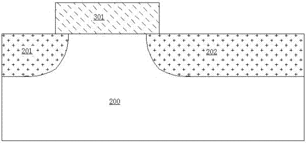
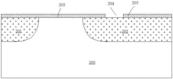
[0038] The present invention will be further described in detail below in conjunction with the accompanying drawings and specific embodiments. In the drawings, the thicknesses of layers and regions are exaggerated for convenience of illustration, and the shown sizes do not represent actual sizes. The referenced figures are schematic illustrations of idealized embodiments of the invention, and the illustrated embodiments of the invention should not be construed as limited to the particular shapes of regions illustrated in the figures but are to include resulting shapes, such as manufacturing-induced deviations. For example, the curves obtained by etching are usually curved or rounded, but in the embodiment of the present invention, they are all represented by rectangles. The representation in the figure is schematic, but this should not be considered as limiting the scope of the present invention. Meanwhile, in the following description, the term substrate used can be understoo...


PUM


Abstract

The invention belongs to the technical field of manufacturing of semiconductor devices and particularly relates to a method for manufacturing a semi-floating gate device with planar channels. The method for manufacturing the semi-floating gate device with the planar channels comprises the steps that the semi-floating gate device with the planar channels is manufactured through a post-gate technology; after a source contact area and a drain contact area are formed, a polycrystalline silicone control gate sacrificial material is removed through etching firstly, secondly a metal control gate material occupies the position originally occupied by the polycrystalline silicone control gate sacrificial material, and then a metal control gate is formed. The metal control gate can be prevented from being damaged in a high-temperature annealing process of a source contact area and a drain contact area, and the performance of the semi-floating gate device with the planar channels is improved. In addition, according to the method, self-alignment technology is adopted to manufacture the source contact area and the drain contact area of the semi-floating gate device, the technology process is simple and stable, and production cost is reduced.

Description

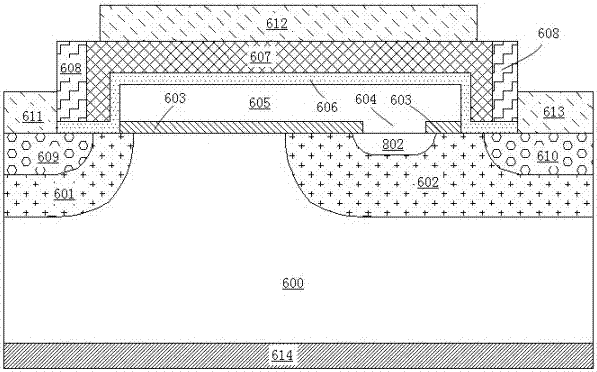
technical field [0001] The invention belongs to the technical field of semiconductor device manufacturing, and in particular relates to a method for manufacturing a planar channel semi-floating gate device. Background technique [0002] A semi-floating gate device with a planar channel proposed in Chinese patent 201310006320.3, its cross-sectional view is as follows figure 1 As shown, the semi-floating gate device of the planar channel includes a source region 601 and a drain region 602 having a second doping type formed in a semiconductor substrate 600 having a first doping type, between the source region 601 and The semiconductor substrate having the first doping type between the drain regions 602 forms a channel region of the device. The first doping type is n-type, and the second doping type is p-type, or, the first doping type is p-type, and the second doping type is n-type. [0003] A gate dielectric layer 603 of the device is formed above the source region 601 , the...

Claims


Application Information

Patent Timeline
Patent Type & Authority Patents(China)
IPC IPC(8): H01L21/336H01L21/28
CPCH01L21/28079H01L29/401H01L29/495H01L29/66545H01L29/66825
Inventor 刘磊刘伟
Owner SUZHOU ORIENTAL SEMICONDUCTOR CO LTD
Learn More