Linear drive based bias current source amplifier system

A bias current source, linear drive technology, applied in the field of electronics, can solve problems such as signal distortion, achieve high sensitivity, low price, and improve the effect of amplification

Inactive Publication Date: 2015-03-25
CHENGDU SIMAO TECH
View PDF0 Cites 6 Cited by
  • Summary
  • Abstract
  • Description
  • Claims
  • Application Information

AI Technical Summary

Problems solved by technology

[0003] The purpose of the present invention is to overcome the defect that the signal amplified by the current amplifier is distorted, and to provide a bias current source amplifier system based on linear drive that can amplify the signal without distortion

Method used


Image

  • Linear drive based bias current source amplifier system
  • Linear drive based bias current source amplifier system

Examples


Embodiment

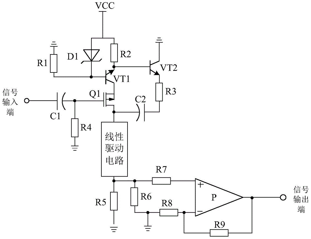
[0015] Such as figure 1 As shown, the bias current source amplifier system based on linear drive of the present invention is mainly composed of field effect transistor Q1, the negative pole is connected to the gate of field effect transistor Q1, the positive pole is used as the polarity capacitor C1 of the signal input end, and one end is connected to the field effect transistor Q1. The gate of the transistor Q1 is connected, the other end is grounded, the resistor R4, the current source circuit connected to the source of the field effect transistor Q1, and the amplifier circuit are connected between the drain of the field effect transistor Q1 and the amplifier circuit. Linear drive circuit.

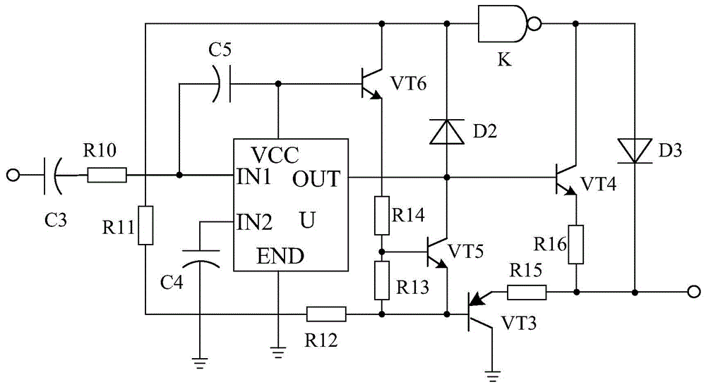
[0016] Such as figure 2 As shown, the linear driving circuit is composed of a driver chip U, a transistor VT3, a transistor VT4, a transistor VT5, and a transistor VT6. The polarity capacitor C3 connected to the feet, one end is connected to the collector of the transistor VT6, and th...


PUM


Abstract

The invention discloses a linear drive based bias current source amplifier system. The linear drive based bias current source amplifier system mainly consists of a field-effect tube Q1, a polar capacitor C1, a resistor R4, a current source circuit and an amplification circuit, wherein the negative pole of the polar capacitor C1 is connected with the grid electrode of the field-effect tube Q1, the positive pole of the polar capacitor C1 serves as a signal input end, one end of the resistor R4 is connected with the grid electrode of the field-effect tube Q1, the other end of the resistor R4 is grounded, and the current source circuit is connected with the source electrode of the field-effect tube Q1. The linear drive based bias current source amplifier system is characterized in that a linear drive circuit is further connected between the drain electrode of the field-effect tube Q1 and the amplification circuit and consists of a drive chip U, an audion VT3, an audion VT4, an audion VT5, an audion VT6 and the like. The linear drive circuit of the linear drive based bias current source amplifier system can stably drive the amplifier system, and accordingly the amplification effect of an amplifier is improved.

Description

technical field [0001] The invention relates to the field of electronics, in particular to a bias current source amplifier system based on linear drive. Background technique [0002] An amplifier is a circuit unit with a very high magnification. In actual circuits, some kind of functional module is usually combined with a feedback network. An amplifier is a circuit unit named from a functional point of view, which can be realized by a discrete device or in a semiconductor chip. With the development of semiconductor technology, most amplifiers exist in the form of a single chip. With the continuous development of electronic technology, amplifiers have been widely used in the electronic industry. However, the currently used amplifiers often cause signal distortion after amplifying the signal, which brings great trouble to the subsequent signal processing. Contents of the invention [0003] The purpose of the present invention is to overcome the defect that the signal amp...

Claims


Application Information

Patent Timeline
Patent Type & Authority Applications(China)
IPC IPC(8): H03F1/32
Inventor 何梅谢彬
Owner CHENGDU SIMAO TECH
Why Eureka
Try Eureka