
Clock signal generating method and system

A clock signal and signal technology, applied in the field of clock signal generation method and system, can solve the problems of low spectral purity and no suppression of DDS output clock signal, etc.

Active Publication Date: 2015-03-25
MIANYANG WEIBO ELECTRONICS
View PDF5 Cites 4 Cited by
  • Summary
  • Abstract
  • Description
  • Claims
  • Application Information

AI Technical Summary

Problems solved by technology

However, its disadvantage is that the output signal contains harmonic components of the fundamental frequency due to the non-linearity of the DAC, that is, the harmonic components or image components falling in the first Nyquist band frequency, which have not been effectively suppressed , the spectral purity of the DDS output clock signal is low

Method used


Image

  • Clock signal generating method and system
  • Clock signal generating method and system
  • Clock signal generating method and system

Examples


Embodiment 1

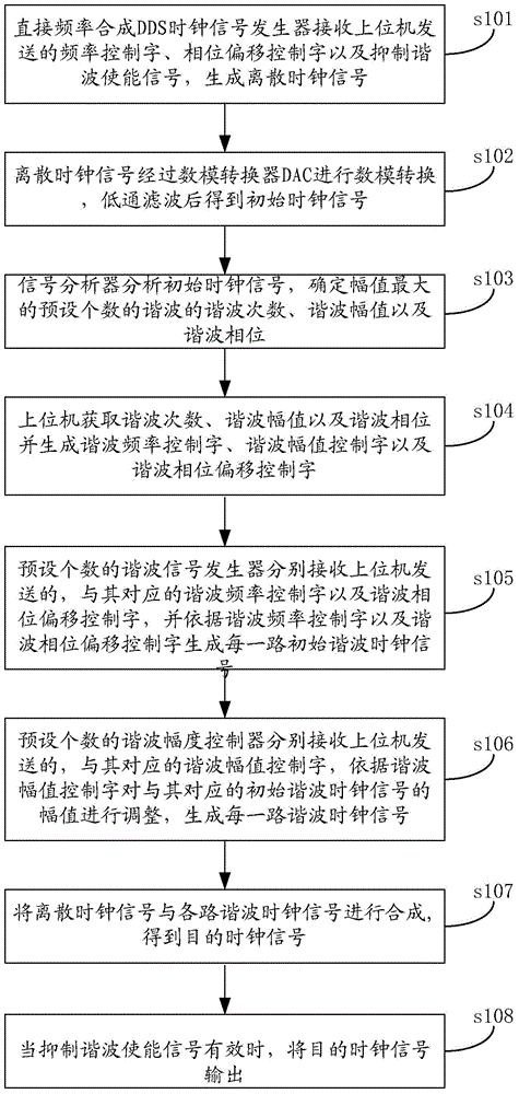
[0048] Please refer to figure 1 , figure 1It is a flow chart of the process of a method for generating a clock signal provided by an embodiment of the present invention, and the method includes:

[0049] Step s101: the direct frequency synthesis DDS clock signal generator receives the frequency control word, the phase offset control word and the suppression harmonic enable signal sent by the host computer, and generates a discrete clock signal;

[0050] It can be understood that the parameter control module of the upper computer is first configured to generate frequency control words, phase offset control words and harmonic suppression enable signals, and transmit them to the direct frequency synthesis DDS clock signal generator, DDS clock signal generator A discrete clock signal is generated under the action of the reference clock signal according to the frequency control word and the phase offset control word.

[0051] Step s102: the discrete clock signal undergoes digital...

Embodiment 2

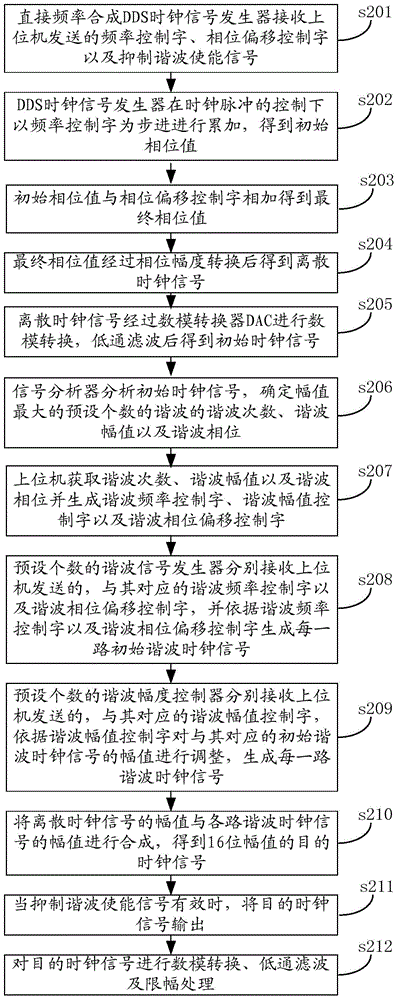
[0071] Please refer to figure 2 , figure 2 The embodiment of the present invention provides a flow chart of another method for generating a clock signal. The method includes:

[0072] Step s201: the direct frequency synthesis DDS clock signal generator receives the frequency control word, phase offset control word and harmonic suppression enable signal sent by the host computer;

[0073] It can be understood that the parameter control module of the upper computer is firstly configured to generate frequency control words, phase offset control words and harmonic suppression enable signals, and transmit them to the direct frequency synthesis DDS clock signal generator.

[0074] Step s202: Under the control of the clock pulse, the DDS clock signal generator accumulates in steps of the frequency control word to obtain the initial phase value;

[0075] It can be understood that every time a reference clock pulse comes, the DDS clock signal generator will take the frequency contr...


PUM


Abstract

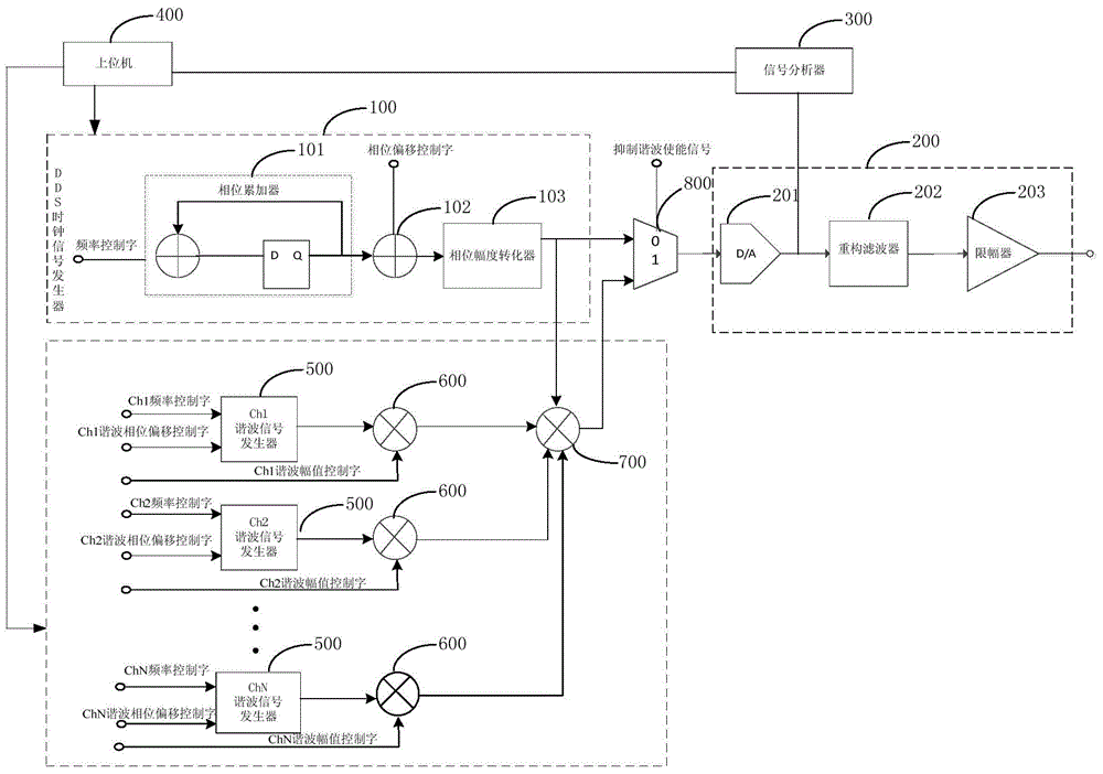
The invention discloses a clock signal generating method and system. The method includes the steps that initial clock signals are generated, the initial clock signals are analyzed to obtain the harmonic wave times, the harmonic wave amplitude value and the harmonic wave phase of a preset number of harmonic waves, then a preset number of harmonic wave signal generators correspondingly receive harmonic wave frequency control words and harmonic wave phase deviation control words sent by an upper computer, and all paths of initial harmonic wave clock signals are generated correspondingly; a preset number of harmonic wave amplitude controllers correspondingly receive harmonic wave amplitude value control words sent by the upper computer, adjust the amplitude of the initial harmonic wave clock signals, and correspondingly generates all the harmonic wave clock signals, so that all the paths of harmonic wave clock signals are made to be the same as the frequency and amplitude value of all the paths of harmonic waves of discrete clock signals, the phase difference is made to be 180 degrees, the purpose of eliminating the harmonic waves is achieved through amplitude value cancellation, the harmonic wave component of the fundamental wave frequency, caused by DAC nonlinear characteristics, in output singles is effectively inhibited, and spectrum purity of DDS output clock signals is improved.

Description

technical field [0001] The invention relates to the field of digital signal processing, in particular to a method and system for generating a clock signal. Background technique [0002] As a new type of frequency synthesis technology, DDS (Direct Digital Synthesizer) is taking advantages of short frequency switching time, high frequency resolution, continuous phase transformation, low phase noise, low drift and wide frequency range. It is increasingly used in electronic systems such as radar, communication, and electronic countermeasures. However, in the frequency synthesis process, the nonlinear characteristics of the digital-to-analog converter DAC (Digital to Analog Converter, that is, the digital-to-analog converter) cause its output signal to contain harmonic components of the fundamental frequency, and these harmonic components will appear in the image The middle reproduction may extend to the first Nyquist band frequency region, which may cause these images to appear...

Claims


Application Information

Patent Timeline
IPC IPC(8): H03L7/24H03M1/10
Inventor 王亨勇卢峥宋方伟张京
Owner MIANYANG WEIBO ELECTRONICS
Learn More