Combined pneumatic control method for aerodynamic rudder/reaction control system of hypersonic flight vehicle

A control system and hypersonic technology, applied in aircraft control, aircraft parts, transportation and packaging, etc., can solve problems such as long response time of aerodynamic rudder control commands, inability to meet the requirements of fast maneuvering flight, and increase the difficulty of aerodynamic shape design , to achieve the effect of improving comprehensive control efficiency and response speed, avoiding adverse effects, and improving comprehensive control efficiency

Active Publication Date: 2015-04-01
BEIHANG UNIV
View PDF4 Cites 11 Cited by
  • Summary
  • Abstract
  • Description
  • Claims
  • Application Information

AI Technical Summary

Problems solved by technology

Aerodynamic rudder surface control is limited by the flight environment, flight angle of attack, maximum trim angle of attack and other flight limit parameters. In high-altitude low-density, low dynamic pressure or high angle of attack flight, the control efficiency of the rudder surface is reduced or even completely fails; the aerodynamic rudder surface The response time of the control command is long (usually on the order of seconds), which is likely to cause a lag in attitude adjustment and cannot meet the requirements of fast maneuvering flight; in addition, due to the limitations of structural weight, aerodynamic heat protection, stealth requirements, etc., it can meet many overall design requirements. Under the premise, the use of aerodynamic rudder surfaces

Method used


Image

  • Combined pneumatic control method for aerodynamic rudder/reaction control system of hypersonic flight vehicle
  • Combined pneumatic control method for aerodynamic rudder/reaction control system of hypersonic flight vehicle
  • Combined pneumatic control method for aerodynamic rudder/reaction control system of hypersonic flight vehicle

Examples


Embodiment 1

[0022] Embodiment 1: pitch control. Given the incoming Mach number Ma ∞ =15, flight altitude H=60km, angle of attack α=0°, 2°, 5°, 8°. Nozzle diameter 4cm, body flap deflection δ m = 8°. Jet pressure ratio P j / P ∞ 100, 500, 1000, 2000 respectively. Amplification factor K of pitching moment under different jet pressure ratio obtained by numerical simulation M Variation with the angle of attack α as Figure 5 shown. It can be seen from the figure that the pitching moment amplification factor increases with the increase of the angle of attack, and all of them are greater than 1, indicating that the jet disturbance produces a positive gain, which improves the control ability of the aerodynamic rudder and reaction control system.

Embodiment 2

[0023] Embodiment 2: roll control. The incoming flow Mach number, height, and angle of attack are the same as in Embodiment 1. The left rudder deflection of the body flap is 8°, and the corresponding pitch and roll rudder deflection angles are δ m = 4°, δ l =-4°. The nozzle diameter and jet pressure ratio are the same as in Example 1. The roll moment amplification factor varies with the angle of attack under different jet pressure ratios as follows: Figure 6 shown. It can be seen from the figure that the amplification factor of the rolling moment increases with the increase of the angle of attack. When the angle of attack is greater than 4°, the amplification factor is greater than 1. When the jet pressure ratio is 100, the amplification factor is greater than that at the calculated angle of attack. 1. The results in the figure show that jet disturbance can produce positive gain and improve the ability of aircraft roll control.

Embodiment 3

[0024] Embodiment 3: Yaw control. The incoming flow Mach number, height, and angle of attack are the same as in Embodiment 1. Body flaps have no deflection. The jet pressure ratio is the same as in Example 1. The magnification factor of yaw moment varies with the angle of attack under different jet pressure ratios as follows: Figure 7 shown. It can be seen from the figure that the amplification factor of the yaw moment decreases with the increase of the angle of attack. Except for the condition of the jet pressure ratio of 2000 and the angle of attack of 8°, the amplification factor of the other conditions is greater than 1, indicating that the jet disturbance has Positive gain, the aircraft yaw control ability is enhanced.


PUM


Abstract

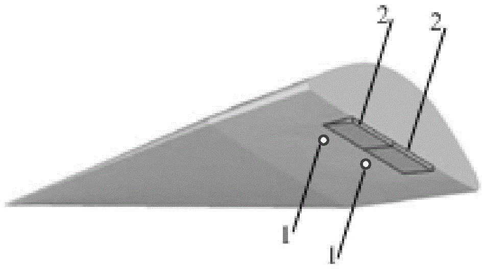
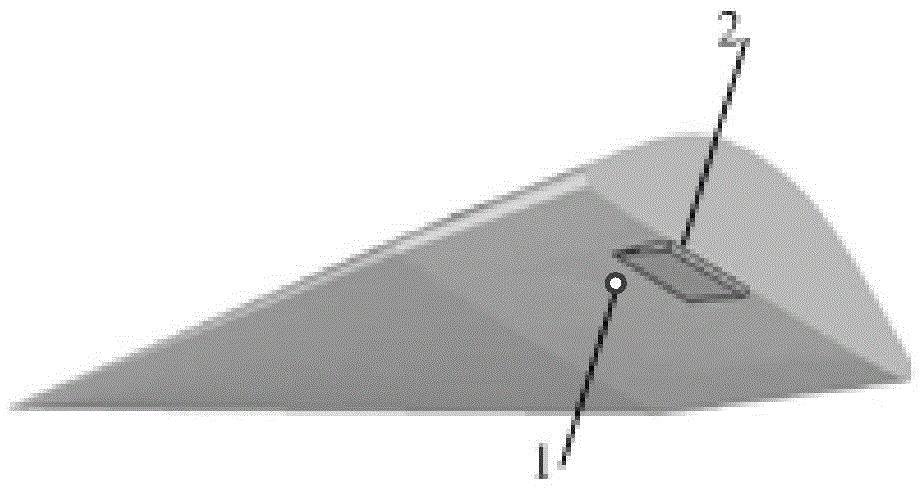
The invention discloses a combined pneumatic control method for an aerodynamic rudder/reaction control system of a hypersonic flight vehicle, and belongs to the field of hypersonic flight vehicle design. As for the hypersonic flight vehicle which has a flat lifting body structure with a flat lower surface and a smaller side edge radius and has a sharp leading edge and a large sweepback body, a pair of expanding type body wing flaps is arranged on the windward side of the lower surface of the rear edge. With adoption of the combined pneumatic control method provided by the invention, reaction control system nozzles are arranged in front of the body wing flaps, pitching control of the flight vehicle is realized through deflection and jet of the body wing flaps, and rolling control of the flight vehicle is realized through differential motion and jet of the body wing flaps; the reaction control system nozzles are arranged on the side edge of the flight vehicle, and yaw control of the light vehicle is realized through jet. Through beneficialinterference of jet flow to the peripheral flow field of the aerodynamic rudder, the comprehensive control efficiency and the response speed of the aerodynamic rudder/reaction control system are increased, and the aerodynamic performance of the flight vehicle is improved. The control method has the characteristics of wide flight application range, high control efficiency and good economy.

Description

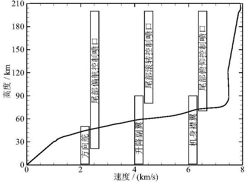
technical field [0001] The invention belongs to the field of hypersonic aircraft design, and in particular relates to a composite aerodynamic control method for an aerodynamic rudder / reaction control system of a hypersonic aircraft. Background technique [0002] A key technology that needs to be solved urgently for hypersonic vehicles is the aerodynamic control problem in hypersonic flight. At present, hypersonic vehicles are controlled by aerodynamic rudder surfaces or reaction control systems (Reaction Control System, RCS), depending on the flight altitude. The so-called reaction control system uses the reaction force generated by the jet to change the attitude or trajectory of the aircraft. Take the space shuttle as an example, such as figure 1 As shown, the RCS system located on both sides of the main engine is at a height H≥81km and an incoming flow Mach number M ∞ Work in the roll direction when ≥27, at H≥69km, M ∞ When ≥22, it works in the pitch direction. Yaw RC...

Claims


Application Information

Patent Timeline
IPC IPC(8): B64C9/00
Inventor 蒋崇文李椿萱高振勋许晨豪杜鹏
Owner BEIHANG UNIV
Why Eureka
Try Eureka