Distribution-source-model-based measuring method of multi-beam depth sounding system complex terrain

A technology of complex terrain and measurement methods, which is applied in the field of offshore oil engineering, can solve problems such as poor accuracy, deterioration of algorithm performance, and inability to estimate angle expansion parameters, so as to achieve the effect of improving detection accuracy and performance

Inactive Publication Date: 2015-04-01
CHINA NAT OFFSHORE OIL CORP +2
View PDF3 Cites 10 Cited by
  • Summary
  • Abstract
  • Description
  • Claims
  • Application Information

AI Technical Summary

Problems solved by technology

However, since the point source model requires that there is only line-of-sight propagation between the source and the receiving array, in the case of complex underwater environments and seabed topography, seabed backscatter signals often have spatial angle diffusion characteristics. Therefore, the actual target It often has more complex spatial distribution characteristics than point sources, and its array flow pattern is affected by the diffusion characteristics of the source. Based on the assumption of point sources, the performance of the source DOA estimation algorithm will be severely deteriorated, thereby reducing the number of sources. Accuracy of beam sounding systems
[0004] In addition, there are two distributed target signal source models: one is: a coherent distributed target signal source based on a determined angular signal density function; the other is: an incoherent distributed target signal source based on a determine...

Method used


Image

  • Distribution-source-model-based measuring method of multi-beam depth sounding system complex terrain
  • Distribution-source-model-based measuring method of multi-beam depth sounding system complex terrain
  • Distribution-source-model-based measuring method of multi-beam depth sounding system complex terrain

Examples


specific Embodiment

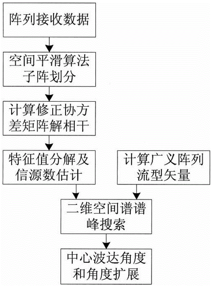
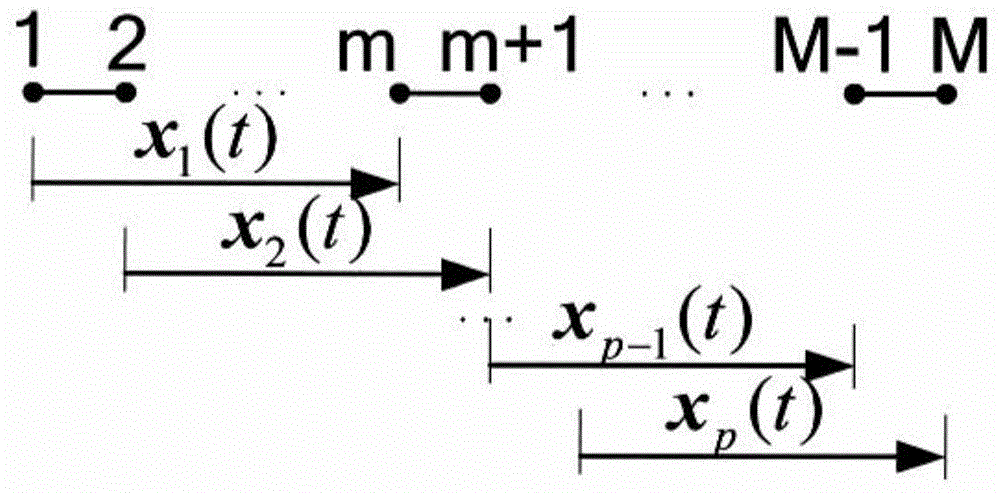
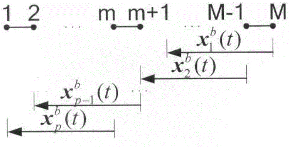
[0068] 1. Such as figure 2 , image 3 As shown, according to the measurement characteristics of the multi-beam bathymetry system, the number of signal sources in the multi-beam bathymetry system is generally two, namely: the left and right sides respectively have seabed scattered echoes, which can be forward smoothing or back In the method of directional smoothing, the receiving array of the multi-beam sounding system is divided into 9 sub-arrays, each of which has 32 elements.

[0069] 2. Take the following forward spatial smoothing algorithm as an example, the calculation formula used by the data matrix of the k-th sub-array is: X k (t)=[x k (t) x k+1 (t)… x k+m-1 (t)], according to the sampling rate f s =40kHz and pulse width tao=0.5ms, take the data length as L=tao×f s =20, the data covariance matrix of the k-th subarray can be calculated by the following formula:

[0070] R k = 1 L X i = 1 L X k X k H

[0071] Average the data covar...


PUM


Abstract

The invention relates to a distribution-source-model-based measuring method of a multi-beam depth sounding system complex terrain. The measuring method comprises the following steps: I, dividing an array received by a multi-beam depth sounding system into a plurality of subarrays which are interlaced; II, calculating a data covariance matrix of the subarrays by a signal processor of the multi-beam depth sounding system to obtain a corrected covariance matrix; III, carrying out characteristic value decomposition on the corrected data covariance matrix, and estimating a signal source quantity to obtain an estimation value of a noise subspace; IV, setting a spatial angle density function conforming to a given distribution of a distribution source, and calculating a generalized array manifold vector according to a specific mathematic form of the given distribution obeyed by the spatial angle density function of the distribution source; V, calculating a two-dimensional spatial spectrum of the distributive signal source, and carrying out the two-dimensional spectrum peak search to obtain the estimated value of an angle and angle extension reached by a center wave. By adopting the method, not only can the complicated seabed terrain be effectively measured, but also the measurement precision of the complicated terrain can be improved.

Description

Technical field [0001] The invention relates to a method for measuring complex terrain, in particular to a method for measuring complex terrain of a multi-beam sounding system based on a distributed source model. It belongs to the field of offshore oil engineering. Background technique [0002] The multi-beam sounding system is a system that transmits narrow-band pulse signals underwater, and uses a sonar array to receive backscatter signals from other scatterers in the seabed and water bodies, and by estimating the echo arrival angle and echo arrival time, A measurement system for obtaining depth information on the seabed. [0003] At present, the existing multi-beam sounding systems all use the joint estimation method of the echo arrival angle and echo arrival time based on the point source model to measure the seafloor depth. The specific method is: assuming that the energy of the source is concentrated in discrete angles, that is, in the direction of arrival, the array flow p...

Claims


Application Information

Patent Timeline
IPC IPC(8): G01C13/00
CPCG01C13/008G01S7/539G01S15/88
Inventor 李志刚李海森周天陈祥余周雷李珊邓平徐超孟元栋魏玉阔陈宝伟李记忠
Owner CHINA NAT OFFSHORE OIL CORP
Why Eureka
Try Eureka