Rotor of permanent magnet synchronous motor and permanent magnet synchronous motor provided with same

A technology for permanent magnet synchronous motors and rotors, which is applied to synchronous motors with stationary armatures and rotating magnets, synchronous machine parts, magnetic circuit rotating parts, etc. Vibration and noise, low utilization rate of permanent magnets and other problems, to achieve the effect of improving anti-demagnetization performance, reducing magnetic flux leakage, and less magnetic flux leakage

Active Publication Date: 2015-04-01
GREE ELECTRIC APPLIANCES INC +1
View PDF8 Cites 21 Cited by
  • Summary
  • Abstract
  • Description
  • Claims
  • Application Information

AI Technical Summary

Problems solved by technology

[0003] However, the tangential permanent magnet motor is easy to form magnetic flux leakage on the inner side close to the rotating shaft. In order to reduce the magnetic flux leakage, it is necessary to install a magnetic isolation bridge inside the rotor. Problems that affect motor performance and motor efficiency, and the increase of magnetic flux leakage will also cause vibration and noise problems of the motor

Method used


Image

  • Rotor of permanent magnet synchronous motor and permanent magnet synchronous motor provided with same
  • Rotor of permanent magnet synchronous motor and permanent magnet synchronous motor provided with same
  • Rotor of permanent magnet synchronous motor and permanent magnet synchronous motor provided with same

Examples


Embodiment 1

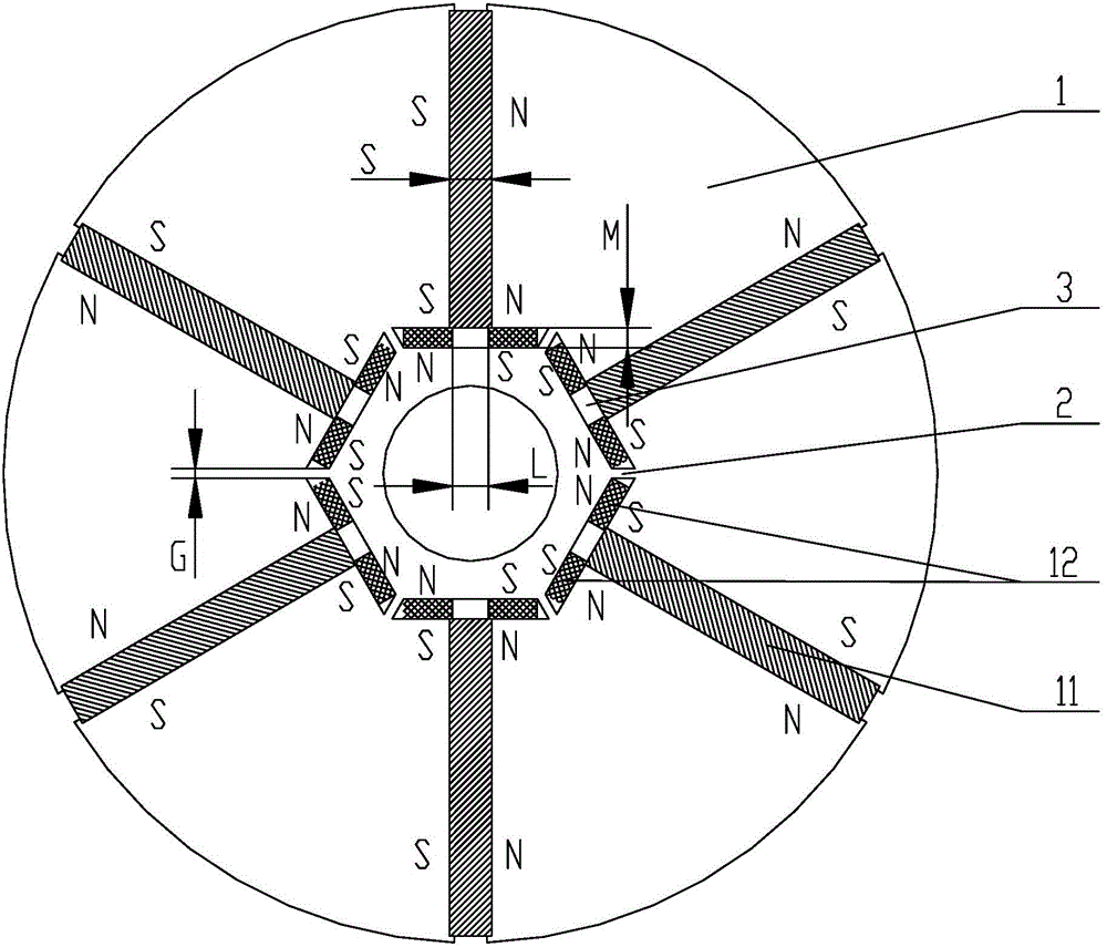
[0039] The present invention provides a permanent magnet synchronous motor rotor, the structure of the permanent magnet synchronous motor rotor is as follows figure 1 , Figure 7 and Figure 8 As shown, it includes a rotor core 1, on which six tangential permanent magnets 11 are evenly distributed in the radial direction, and the same polarity of two adjacent tangential permanent magnets 11 is opposite, that is to say, one tangential One side of the permanent magnet 11 is an N pole (or S pole), and the other tangential permanent magnet 11 side close to this side and opposite to it is also an N pole (or S pole). A radial permanent magnet 12 is arranged symmetrically on both sides of one end of each tangential permanent magnet 11 near the inner side of the rotor core 1 . The two radial permanent magnets 12 sandwiched between two adjacent tangential permanent magnets 11 have the same polarity facing the stator direction, which is the same as the polarity of the adjacent side of...

Embodiment 2

[0046] This embodiment provides a permanent magnet synchronous motor rotor, the structure of which is basically the same as that of the rotor described in Embodiment 1, and will not be repeated here.

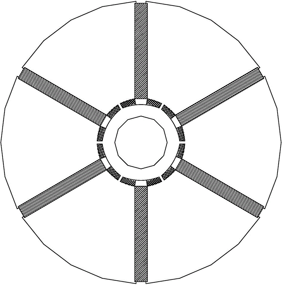
[0047] The difference is that: if figure 2 As shown, the cross-sectional shape of each radial permanent magnet is arc-shaped, and further, the arc-shaped is an arc-shaped straight bar, and the arc-shaped straight bar has two arc-shaped sides and oppositely arranged The two straight sides, and the two arc-shaped sides are arranged along the circumference of the rotor, and the two straight sides are arranged along the radial direction of the rotor.

Embodiment 3

[0049] This embodiment provides a permanent magnet synchronous motor rotor, the structure of which is basically the same as that of the rotor described in Embodiment 1, and will not be repeated here.

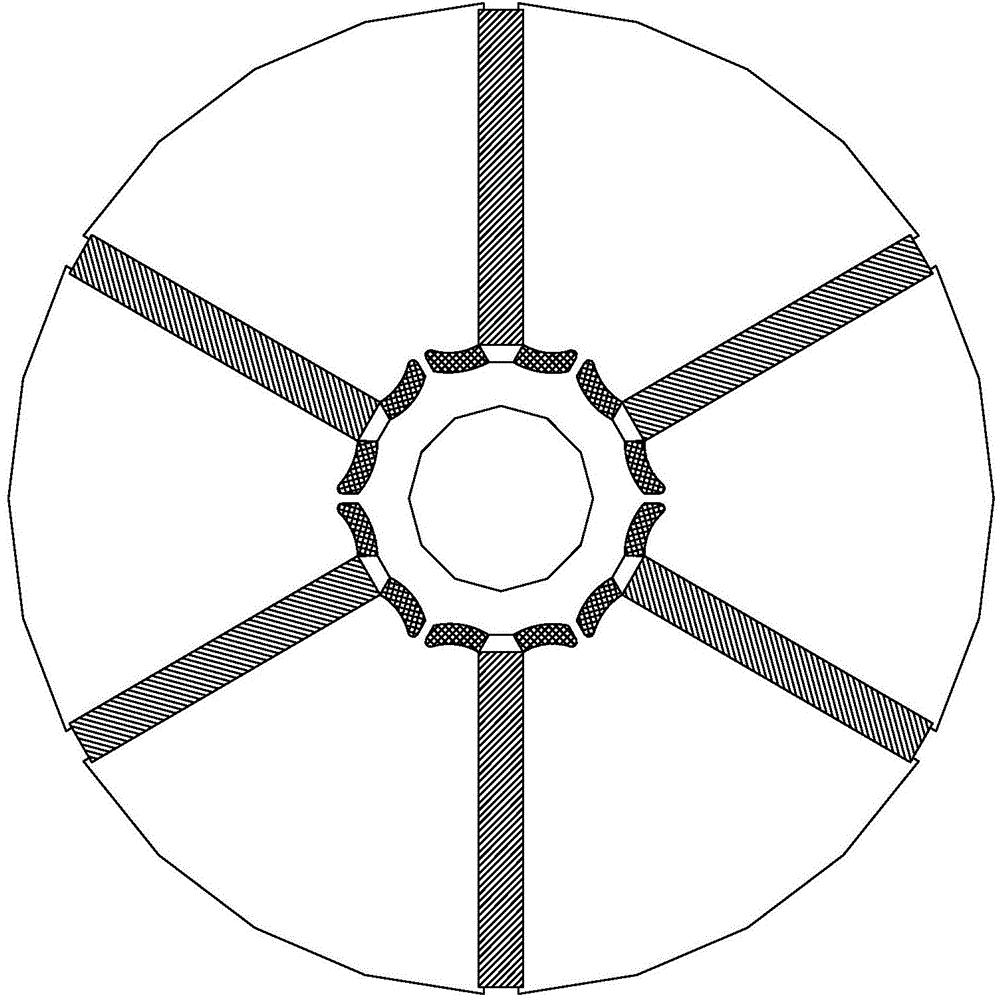
[0050] The difference is that: if image 3 As shown, the cross-sectional shape of each radial permanent magnet is a curved arc, further, the curved arc is an arc-shaped curved bar, and the arc-shaped curved bar has two sets of curved arc-shaped sides, one of which is set opposite and two curved sides arranged along the rotor circumference, and the other group is two curved sides arranged opposite and arranged radially along the rotor.


PUM


Abstract

The invention discloses a rotor of a permanent magnet synchronous motor and the permanent magnet synchronous motor, which belong to the technical field of the permanent magnet synchronous motors, and are designed in order to solve the problems of high leakage flux, low permanent magnet utilization rate, influence on motor performance and efficiency and the like in existing rotor of the permanent magnet synchronous motor. The rotor of the permanent magnet synchronous motor comprises a rotor core, wherein an even number n of tangential permanent magnets are distributed evenly in radial direction on the rotor core, and the same polarities of two adjacent tangential permanent magnets are opposite; radial permanent magnets are arranged symmetrically on two sides of one end of each tangential permanent magnet close to the inner side of the rotor core respectively; every two radial permanent magnets sandwiched between two adjacent tangential permanent magnets have the same polarity in the direction facing to a stator, and a magnetic isolating bridge is arranged between every two radial permanent magnets. The invention further discloses a permanent magnet synchronous motor provided with the rotor. By utilizing the rotor, the leakage flux of the tangential permanent magnets on the inner side of the rotor is reduced, the utilization rate of the permanent magnets is improved, and the motor efficiency and the motor structural intensity are enhanced.

Description

technical field [0001] The invention belongs to the technical field of permanent magnet synchronous motors, in particular to a permanent magnet synchronous motor rotor and a permanent magnet synchronous motor with the rotor structure. Background technique [0002] The motor with tangential magnetization structure of permanent magnet has the effect of "magnetism concentration", which can produce higher air gap flux density than radial structure, so that the motor has a larger torque / current ratio and torque / volume ratio, and the more It is more and more used in servo systems, electric traction, office automation, household appliances and other occasions. [0003] However, tangential permanent magnet motors tend to form magnetic flux leakage on the inner side close to the rotating shaft. In order to reduce magnetic flux leakage, it is necessary to install a magnetic isolation bridge inside the rotor. Even if a magnetic isolation bridge is installed, there is still a large magn...

Claims


Application Information

Patent Timeline
Patent Type & Authority Applications(China)
IPC IPC(8): H02K1/27H02K21/02
CPCH02K1/2706H02K21/14
Inventor 肖勇李小飞
Owner GREE ELECTRIC APPLIANCES INC
Why Eureka
Try Eureka