
Diluting spiral for conveying straw papermaking slurry

A slurry conveying and straw technology, applied in packaging, grain processing, etc., can solve the problems of lowering the efficiency of subsequent steps, difficult to meet the requirements of the conveying screw, easy to imagine, etc., and achieve the effect of avoiding poor product quality

Active Publication Date: 2015-04-08
昌邑润德生态纤维有限公司
View PDF6 Cites 6 Cited by
  • Summary
  • Abstract
  • Description
  • Claims
  • Application Information

AI Technical Summary

Problems solved by technology

Although the literature proposes to use biotechnology to process black liquor, it is not difficult to find that this method of cooking straw to process plant stalks results in a large amount of black liquor and is difficult to handle
[0005] 2. In the document "Research on the Application of Corn Stalks in the Pulp and Paper Industry", a method for pulping corn stalks with caustic soda-anthraquinone is provided. The specific process is as follows: Figure 5 As shown, however, this method mainly uses chemical reagents to treat straw. It is not difficult to imagine that the later wastewater treatment is very complicated, and the use of chlorination bleaching will produce toxic organic chlorides, which is difficult to apply to large-scale production.
[0008] In the above process steps, conveying the pulp after pulp washing to the subsequent steps requires the use of a conveying screw. However, in view of the particularity of straw production pulp, the traditional conveying screw is difficult to meet the requirements
This is because: 1. The pulp concentration of straw papermaking is relatively high, and the agglomeration is serious after pulp washing. If the lumpy straw pulp is simply transported to the subsequent process, the efficiency of the subsequent steps will be greatly reduced. It even affects the quality of the final product; 2. The traditional conveying screw cannot realize the function of conveying and diluting

Method used

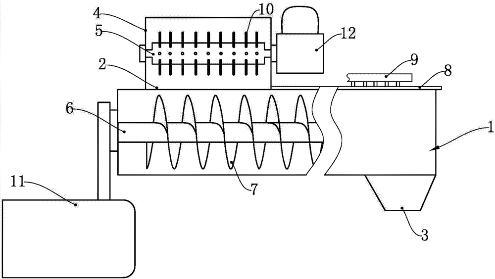

Image

  • Diluting spiral for conveying straw papermaking slurry
  • Diluting spiral for conveying straw papermaking slurry
  • Diluting spiral for conveying straw papermaking slurry

Examples


Embodiment Construction

[0039] In order to make the technical means, creative features, goals and effects achieved by the present invention easy to understand, the present invention will be further described below in conjunction with specific illustrations.

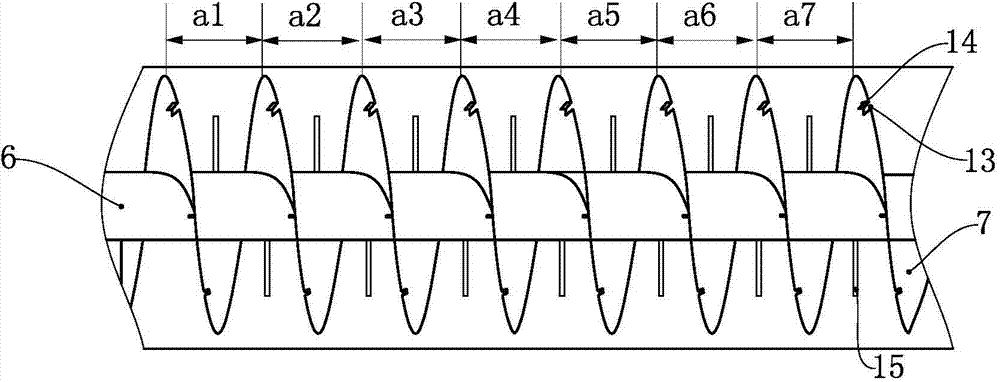
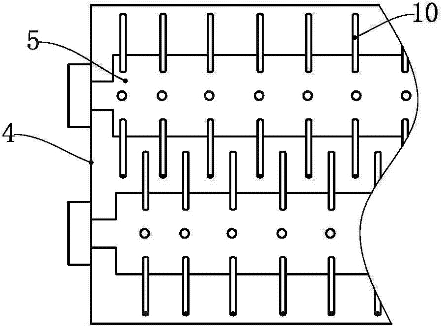
[0040] Such as figure 1 , figure 2 and image 3 As shown, a dilution screw for conveying straw papermaking slurry includes a conveying tank 1, the conveying tank 1 is provided with a feed port 2 and a discharge port 3, and a feed tank body 4 is installed on the feed port 2 , the toothed crushing roller 5 is installed in rotation in the feed tank body 4, the toothed crushing roller 5 is provided with two, arranged in parallel with each other, the inside of the conveying trough 1 is equipped with a rotating shaft 6, the rotating The shaft 6 is provided with a helical blade 7, and the blade pitch of the helical blade 7 in the front section of the rotating shaft 6 gradually increases, and the blade pitch of the helical blade 7 in the latter sect...


PUM


Abstract

The invention discloses a diluting spiral for conveying straw papermaking slurry; the diluting spiral disclosed by the invention comprises a conveying groove; a feeding hole and a discharging hole are formed in the conveying groove; a feeding groove body is formed in the feeding hole; two tooth type crushing rollers are rotatably installed in the feeding groove body; the two tooth type crushing rollers are arranged in parallel; a rotating shaft is installed in the conveying groove; spiral blades are arranged on the rotating shaft; the spaces among the front sections of the spiral blades of the rotating shaft are gradually increased; the spaces among the rear sections of the spiral blades of the rotating shaft are equal; a cover plate is arranged at the upper part of the conveying groove; a water spraying pipe is installed on the cover plate; the diluting spiral further comprises driving equipment; and the driving equipment is in power connection with the tooth type crushing rollers and the rotating shaft respectively. According to the diluting spiral, the requirement of conveying the slurry while diluting in the straw papermaking process is satisfied; and furthermore, the problem of being poor in quality caused by that the slurry is aggregated and enters the subsequent steps in the straw papermaking process is avoided.

Description

technical field [0001] The invention relates to papermaking raw material processing equipment, in particular to a conveying screw, in particular to a dilution screw suitable for conveying straw papermaking slurry. Background technique [0002] At present, wood is generally used as the main raw material in the paper industry, but with the further deterioration of the environment, this process of using logs as raw materials is gradually being replaced. In order to meet the needs of the paper industry to the greatest extent, there are now gradually emerging The technology of wool grass, cotton stalks, reeds, corn stalks, straw and other grasses as raw materials for pulping not only provides a new fiber source for the paper industry, but also realizes the utilization of waste, changing the original above-mentioned materials that can only be incinerated. Or returning to the field, the comprehensive utilization of resources has been realized, which has excellent social and economi...

Claims


Application Information

Patent Timeline
IPC IPC(8): B02C4/08B02C4/30B65G33/26B65G33/14
CPCB02C4/08B02C4/30B65G33/14B65G33/265
Inventor 邝嘉龙毛振峰侯珍珍夏书娟王天利
Owner 昌邑润德生态纤维有限公司
Learn More