Electron beam melting and laser milling composite 3D printing apparatus

A technology of electron beam melting and laser milling, which is applied in the direction of laser welding equipment, welding equipment, metal processing equipment, etc., can solve the problems of large processing error, part variability, and difficult clamping, so as to improve precision and avoid clamping difficulties , the effect of broad application space

Inactive Publication Date: 2015-04-08
YUANMENG PRECISION TECH SHENZHEN INST
View PDF10 Cites 17 Cited by
  • Summary
  • Abstract
  • Description
  • Claims
  • Application Information

AI Technical Summary

Problems solved by technology

[0008] The purpose of the present invention is to provide electron beam melting and laser milling composite 3D printing equipment, aiming to solve the problem of secondary processing of parts processed by metal melting 3D printing technology on machine tools in the prior art, which has difficulties in clamping, large processing errors, Part variability and difficulty in processing

Method used


Image

  • Electron beam melting and laser milling composite 3D printing apparatus
  • Electron beam melting and laser milling composite 3D printing apparatus

Examples


Embodiment Construction

[0022] In order to make the object, technical solution and advantages of the present invention clearer, the present invention will be further described in detail below in conjunction with the accompanying drawings and embodiments. It should be understood that the specific embodiments described here are only used to explain the present invention, not to limit the present invention.

[0023] The implementation of the present invention will be described in detail below in conjunction with specific embodiments.

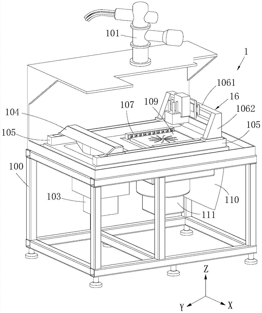
[0024] like Figure 1~2 Shown is the preferred embodiment provided by the present invention.

[0025] The 3D printing device 1 provided by the present invention combines laser milling and electron beam melting, and can be used to form various parts, such as parts required by the aviation manufacturing industry.

[0026] Electron beam melting and laser milling composite 3D printing equipment 1 includes a base 100, a powder spreading structure, an electron beam emitting s...


PUM


Abstract

The invention relates to the technical field of 3D printing apparatus and discloses an electron beam melting and laser milling composite 3D printing apparatus. The3D printing apparatus comprises a base on which a machining platform is arranged; a powder spreading structure for spreading a metal powder on the machining platform is arranged on the base; an electron beam emitting structure and a laser milling head are arranged above the machining platform, respectively; the electron beam emitting structure emits an electron beam to melt the metal powder layer so as to form a single-layer or multi-layer approximate body; the laser milling head emits a laser beam to perform milling machining on the single-layer or multi-layer approximate body. The 3D printing apparatus is integrated with the removal machining taking laser milling as the principal method and the incremental laminating manufacturing process with electron beam melting 3D printing as the principal method, and therefore, the defects of the 3D printing technology in the aspects such as size and shape are overcome, the restriction of cutting to the complexity of parts and the like is overcome, the machined parts do not need to be machined secondarily, and the problems of difficult clamping, large machining error, part deformation during machining and difficult machining are avoided.

Description

technical field [0001] The invention relates to the technical field of 3D printing equipment, in particular to electron beam melting and laser milling composite 3D printing equipment. Background technique [0002] Metal melting 3D printing technology (Selective Laser Melting, SLM) uses high-brightness laser to directly melt metal powder materials without binders, and directly forms arbitrary complex structural parts with the same performance as castings from 3D models. [0003] Although metal fusion 3D printing technology can form parts that reach the casting strength level, the shape error of the formed parts is large and the surface finish is not high. In this way, the formed parts need to be processed twice by traditional machining methods. Only by processing can the shape and surface accuracy required by the aviation manufacturing industry be obtained. However, most parts in the aerospace industry, such as engine nozzles, blades, honeycomb structure combustion chambers,...

Claims


Application Information

Patent Timeline
Patent Type & Authority Applications(China)
IPC IPC(8): B22F3/105B23K26/38
CPCY02P10/25
Inventor 欧阳渺安徐毅李军旗聂炎
Owner YUANMENG PRECISION TECH SHENZHEN INST
Why Eureka
Try Eureka