Numerical controlmolding clamp and molding method for medium/small caliber planar optical component

An optical part, small diameter technology, applied in the field of CNC molding fixture and molding, can solve problems such as insufficient adsorption force, optical parts burst, increase fixture manufacturing cost, etc., to solve the problem of easy sliding and falling off, increase friction coefficient, and improve molding accuracy Effect

Inactive Publication Date: 2015-04-08
THE 3RD ACAD 8358TH RES INST OF CASC
View PDF7 Cites 2 Cited by
  • Summary
  • Abstract
  • Description
  • Claims
  • Application Information

AI Technical Summary

Problems solved by technology

Bonding is the most widely used clamping method. The required fixture is relatively easy to implement, but it needs to be heated during the bonding process. If it is not done properly, it will cause the optical parts to burst. The operation is cumbersome, the positioning accuracy is limited, and the efficiency is low. ; Although the vacuum adsorption tooling is easy to operate during processing, it needs to be equipped with a special vacuum adsorption device, and the fixture needs to have a specially designed sealing structure. For small-caliber optical parts, due to the limited force-bearing area and insufficient adsorption force, the process It is prone to loosening and other phenomena that affect the machining accuracy of parts, and even parts fall off. Mechanical clamping is widely used in CNC edging machines. cutting edge, and polishing treatment, which increases the manufacturing cost of the fixture
On the other hand, the friction coefficient between the polished cutting edge and the polished surface of the part is very low, and the friction force is limited. It is easy to cause the part to loosen or even fall off during the processing. For some soft materials, such as ZnS, etc., if the pressure is too high Large, the polished cutting edge will produce indentations on the surface of the part, which will affect the surface finish of the part and cannot meet the design requirements

Method used


Image

  • Numerical controlmolding clamp and molding method for medium/small caliber planar optical component
  • Numerical controlmolding clamp and molding method for medium/small caliber planar optical component
  • Numerical controlmolding clamp and molding method for medium/small caliber planar optical component

Examples


Embodiment 1

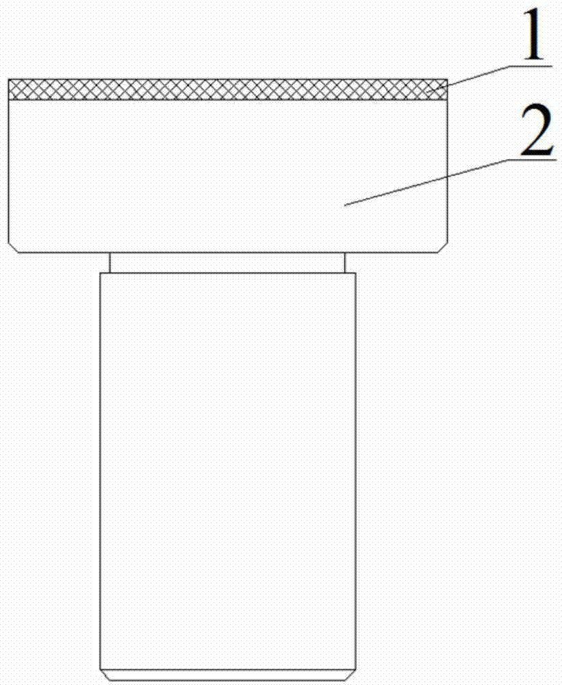
[0029] The schematic diagram of the numerical control molding fixture structure of the small and medium-caliber planar optical parts of this embodiment is as follows figure 1 As shown, the numerical control forming fixture includes a protective pad 1 and a fixture seat 2 .

[0030] Specifically, the fixture seat 2 includes a connection head connected to the machine tool spindle at the lower end and a clamping head at the upper end for effectively clamping the optical parts. The connection head is a cylindrical solid formed by precision turning; The diameter of the circle should be greater than the diameter of the connecting head, and the lower end surface is perpendicular to the axis of the connecting head; the upper end surface of the clamping head is circular or similar in shape to the clamped surface of the planar optical part; when the upper end surface of the clamping head When it is circular, its diameter is smaller than the diameter of the inscribed circle of the clampe...

Embodiment 2

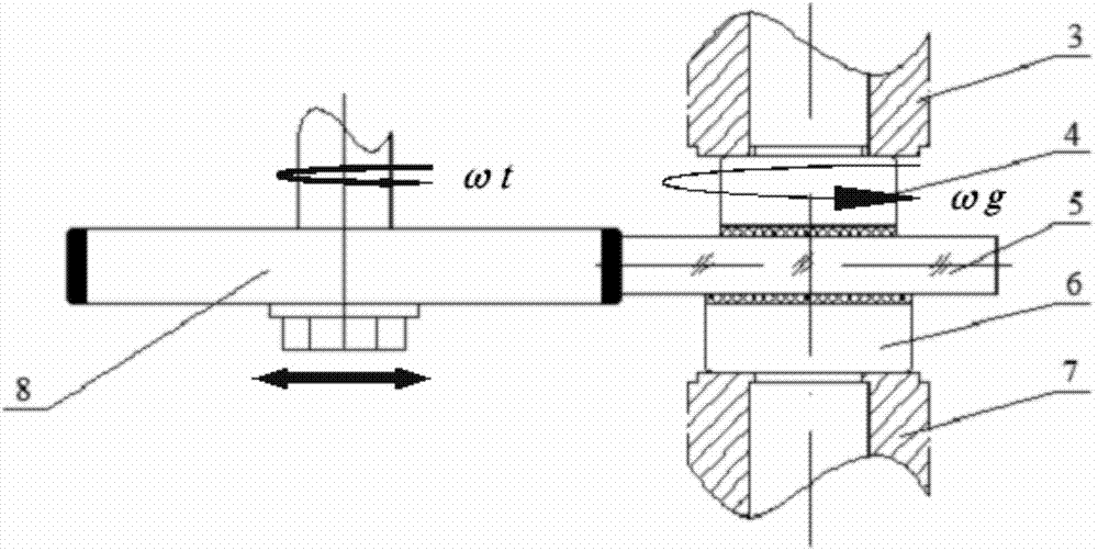
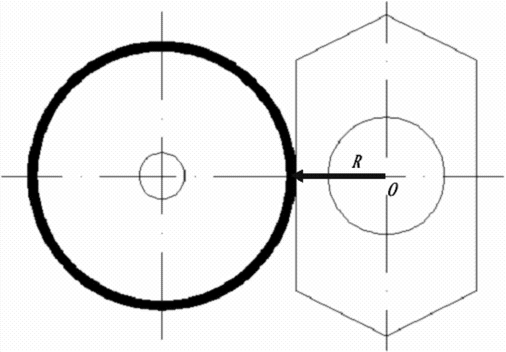
[0034] Embodiment 2 is a method of precisely numerically-controlled forming a flat optical part on a numerically-controlled edging machine using the jig described in Embodiment 1. Such as figure 2 As shown, the method for processing a flat optical part 5 from a circular blank into a required hexagon, the specific steps are as follows:

[0035] a. Turn on the machine tool, and fix the upper fixture 4 and the lower fixture 6 matching the surface size of the clamped part into the upper spindle base 3 and the lower spindle base 7 of the numerical control equipment respectively;

[0036] b. Place the blank of the planar optical part 5 on the protective pad of the lower fixture 6 to find the correct position, set and adjust the upper fixture 4 to move down and press the planar optical part 5 to an appropriate pressure; wherein, the method of finding the alignment adopts the table method Or use the grinding wheel to directly hit the positioning method.

[0037] c. Data input progr...


PUM


Abstract

The invention belongs to the field of cold working of optical elements, and discloses a numerical controlmolding clamp and a molding method for a medium / small caliber planar optical component. The numerical controlmolding clamp comprises a protecting pad layer (1) and a clamp base (2), wherein the clamp base (2) comprises a connecting head of which the lower end is connected with a machine tool main shaft, and a clamping head of which the upper end is used for effectively clamping the optical component; the protecting pad layer (1) is adhered to the upper end surface of the connecting head of the clamp base (2) by using an adhesive. The numerical controlmolding clamp is simple and reasonable in structure and convenient to operate, and is applicable to numerical controlmolding of planar optical components, and particularly applicable to precise numericalcontrol molding of medium / small caliber planar optical components on a numerical control centering edging machine; due to adoption of the protecting pad layer, the friction coefficient between clamps and an optical surface is increased, the friction is increased under the condition of equal clamping force, the problem that the optical component is easy to slide and drop off in numerical control molding is effectively solved, and the molding precision of the medium / small caliber planar optical component is improved.

Description

technical field [0001] The invention belongs to the field of cold processing of optical elements, and in particular relates to a numerical control forming fixture and a forming method of small and medium-diameter plane optical parts. Background technique [0002] Planar optical parts are often used as reflectors, folding mirrors, various windows, etc., and are one of the most widely used optical parts in various optical systems. In order to meet the needs of the optical system, the shape of planar optical parts is often designed with different precision, especially when used as a window, the shape and position accuracy is very high, which brings severe challenges to the molding processing technology. [0003] In the existing technology, the shape of planar optical parts is mainly processed by CNC milling and grinding with fixed abrasive diamond grinding wheel on equipment such as CNC milling and grinding machines, and the commonly used clamping methods are divided into bondi...

Claims


Application Information

Patent Timeline
Patent Type & Authority Applications(China)
IPC IPC(8): B24B13/005B24B13/00
CPCB24B13/0055B24B13/00
Inventor 王朋回长顺张昊
Owner THE 3RD ACAD 8358TH RES INST OF CASC
Why Eureka
Try Eureka