
Composite high-order cycloidal planetary transmission device

A planetary transmission, high-level technology, applied in transmissions, gear transmissions, transmission parts, etc., can solve the problems of tedious selection and calculation of gear geometric parameters, less practical experience, and difficult to guarantee accuracy.

Inactive Publication Date: 2015-04-08
CHONGQING UNIV
View PDF6 Cites 1 Cited by
  • Summary
  • Abstract
  • Description
  • Claims
  • Application Information

AI Technical Summary

Problems solved by technology

Although there are many types of existing reducers, they all have relatively large limitations: for example, ordinary cylindrical gear reducers are bulky and heavy in structure; ordinary worm gear reducers have the problem of low efficiency when the transmission ratio is large; Planetary reducers with small tooth difference are prone to various interferences. In order to avoid interference, the gear pair needs to adopt a large displacement coefficient and transmission meshing angle. Therefore, the selection and calculation of gear geometric parameters in the design process are quite cumbersome , the precision requirements for the output mechanism are also high. In addition, because this type of high-power reducer is mostly in the theoretical stage, there is little practical experience, and there are still some difficulties in practical application; although the cycloid planetary reducer can meet the above requirements , but its tooth shape is difficult to process, the precision is difficult to be guaranteed, and its processing cost is high, which is not conducive to large-scale application; for cycloidal planetary transmission, there are low service life of the arm bearing, high requirements for uniform distribution of pin teeth, and fan-shaped hole output The machining accuracy of the mechanism is high. In addition, the manufacture of the mechanism requires the use of special equipment, which greatly increases the manufacturing cost.

Method used


Image

  • Composite high-order cycloidal planetary transmission device
  • Composite high-order cycloidal planetary transmission device
  • Composite high-order cycloidal planetary transmission device

Examples


Embodiment Construction

[0024] The preferred embodiments of the present invention will be described in detail below with reference to the accompanying drawings.

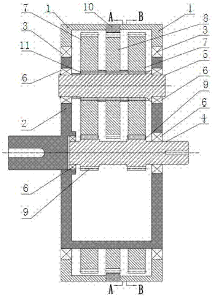
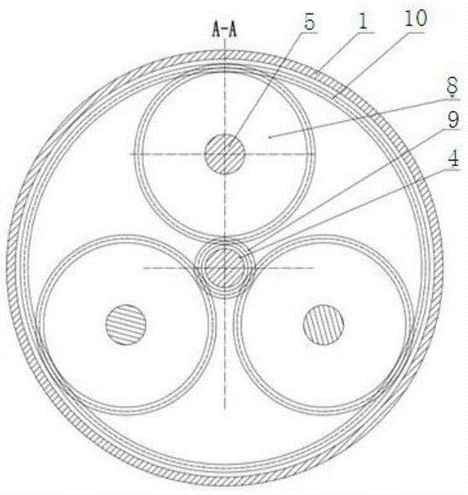
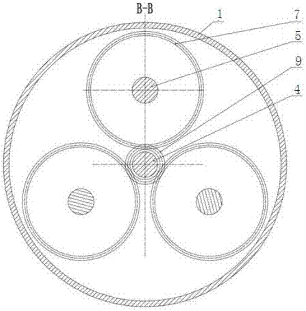
[0025] As shown in the figure, the composite high-order cycloidal planetary transmission device in this embodiment includes a box body 1 and a planet carrier 2, and the planet carrier 2 is arranged on the box body 1 through a supporting bearing 3; the planet carrier 2 An input shaft 4 and several planetary shafts 5 are arranged on the top, and each planetary shaft 5 is evenly distributed around the input shaft 4, and the planetary shafts 5 and the input shafts 4 are supported and fixed on the planet carrier 2 through bearings 6; each planetary shaft 5 The involute planetary gear 7 and the high-order cycloid planetary gear 8 are fixed on it, the sun gear 9 is correspondingly fixed on the input shaft 4, the ring gear 10 is correspondingly fixed on the box body 1, and the involute planetary The gear 7 meshes with the sun gear 9 and the high-or...


PUM


Abstract

The invention discloses a composite high-order cycloidal planetary transmission device which comprises a box body and a planetary carrier. The planetary carrier is arranged on the box body through a supporting bearing. An input shaft and a plurality of planetary shafts are arranged on the planetary carrier, the planetary shafts are evenly distributed around the input shaft, and the planetary shafts and the input shaft are fixed to the planetary carrier through bearing supports. Involute planetary wheels and high-order cycloidal planetary wheels are fixed to the planetary shafts, sun wheels are correspondingly fixed to the input shaft, gear rings are correspondingly fixed to the box body, the involute planetary wheels are meshed with the sun wheels, and the high-order cycloidal planetary wheels are meshed with the gear rings. The composite high-order cycloidal planetary transmission device has the advantages of being compact in structure, high in bearing capacity, high in contact strength, low in sliding rate, high in torsion rigidity, good in impact resisting performance and the like, and the defects of application limitation in the prior art are overcome.

Description

technical field [0001] The invention belongs to the field of speed reducers, and in particular relates to a compound high-order cycloid planetary transmission device. Background technique [0002] With the development of modern industry and the continuous improvement of the level of mechanization and automation, more and more reducers are required in various industrial sectors, and the requirements for reducers are small in size, light in weight, large in transmission ratio, high in efficiency, and large in carrying capacity. Reliable operation and long service life are required. Although there are many types of existing reducers, they all have relatively large limitations: for example, ordinary cylindrical gear reducers are bulky and heavy in structure; ordinary worm gear reducers have the problem of low efficiency when the transmission ratio is large; Planetary reducers with small tooth difference are prone to various interferences. In order to avoid interference, the gea...

Claims


Application Information

Patent Timeline
IPC IPC(8): F16H1/32F16H57/023F16H57/021F16H57/08
CPCF16H1/32F16H55/17F16H57/021F16H57/023F16H57/08F16H2700/00
Inventor 石万凯韩振华李良军肖洋轶
Owner CHONGQING UNIV
Learn More