Pipe and flange connection structure and processing method thereof

A technology of connection structure and processing method, applied in the direction of flange connection, pipe/pipe joint/pipe fitting, passing element, etc., can solve the problems of affecting the eyes, affecting the life of the operator, processing danger, etc., to avoid irritating gas and dazzling eyes. The effect of fire light, avoiding the complicated process of the brazing furnace and reducing the working intensity

Inactive Publication Date: 2015-04-08
NINGBO T ERRE AUTOMOTIVE COMPONENTS
View PDF7 Cites 8 Cited by
  • Summary
  • Abstract
  • Description
  • Claims
  • Application Information

AI Technical Summary

Problems solved by technology

[0006] 1. Spot welding will produce a large amount of irritating gas during the welding process, and there will be dazzling flames. These irritating gases will cause great harm to personal health and will affect the life of operators in the long run; these dazzling flames will Affecting the eyes of the operator will seriously affect the normal service life of the operator's eyes if things go on like this; moreover, a little improper operation will directly affect the personal safety of the operator, which can easily cause work-related injuries; The processing method of the connection structure of the flange has the disadvantages of processing danger and great harm to the operator's body;
[0007] 2. After the spot welding, the connection structure of the pipe and the flange needs to pass through the brazing furnace to improve its overall performance. The brazing furnace is a kind of equipment used for metal brazing and bright heat treatment, which is suitable for mass production. Small stainless steel parts (tableware, knives, hardware, etc.), such as bright quenching and tempering of martensitic stainless steel, bright annealing of austenitic stainless steel; the components of the brazing furnace are: degreasing furnace→spray system→drying transmission→drying Furnace → passive drying, passive brazing → front chamber → brazing furnace → water cooling (dry cooling) → strong air cooling → brazing furnace drive; finally, it is also necessary to seal the end face of the connection structure between the pipe and the flange ; Thereby it can be seen that the processing method of this pipe and the connection structure of the flange has the disadvantages of complex manufacturing process and long production cycle

Method used


Image

  • Pipe and flange connection structure and processing method thereof
  • Pipe and flange connection structure and processing method thereof
  • Pipe and flange connection structure and processing method thereof

Examples


specific Embodiment approach

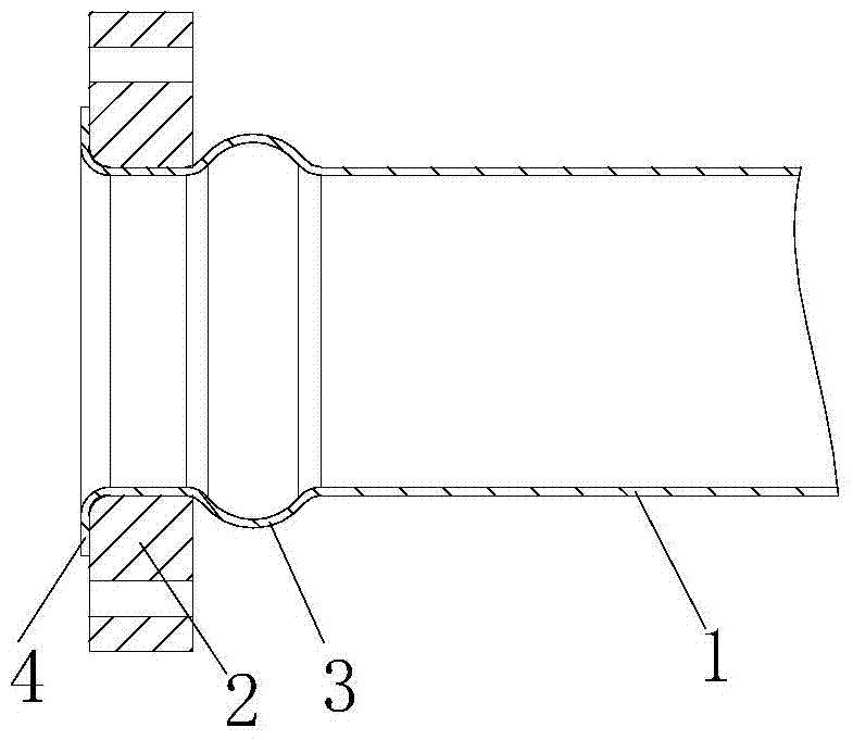
[0027] A connection structure between a pipe and a flange, which includes a pipe 1 and a flange 2 sleeved on the end of the pipe, the pipe 1 inside the flange 2 is a convex ring 3 that expands radially outward, and the pipe 1 outside the flange 2 The flange 2 is pressed against the flange 3 by the flange 4 which expands radially outwards. The protruding ring 3 looks like an annular bulge in the actual pipe fitting.

[0028] The flange 4 is also provided with a plurality of connecting holes for connecting with external pipe fittings.

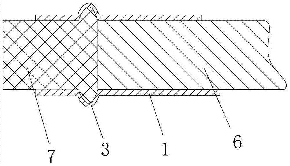
[0029] A glass fiber mesh cloth is arranged between the outer wall of the flange 2 and the outer wall of the pipe 1, and a glass fiber mesh cloth is arranged between the outer wall of the flange 2 and the outer wall of the convex ring 3. Glass fiber mesh cloth has the advantages of alkali resistance, flexibility, and high warp and weft tensile strength, and also has the functions of heat preservation, crack resistance, and waterproof. Therefore,...


PUM

PropertyMeasurementUnit
tensile strengthaaaaaaaaaa
elongationaaaaaaaaaa

Abstract

The invention discloses a pipe and flange connection structure and a processing method thereof. The pipe and flange connection structure comprises a pipe (1) and a flange (2) sleeving the end of the pipe, the pipe (1) inside the flange (2) is provided with a convex ring (3) expanding outwards radially, the pipe (1) outside the flange (2) is provided with a flanging (4) expanding outwards radially, and the flange (4) is tightly pressed onto the convex ring (3) by the flanging (4). The pipe and flange connection structure is low in production cost, and the processing method of the pipe and flange connection structure is low in harms to bodies of operators, simple in manufacturing process and short in production cycle.

Description

technical field [0001] The invention relates to the technical field of connection structures between pipes and flanges, in particular to a connection structure between pipes and flanges and a processing method thereof. Background technique [0002] The existing connection structure between the pipe and the flange is a transition joint for connection, which is composed of a flange and a pipe. The flange is welded to the end of the pipe, and the end face of the flange used to cooperate with other pipes is provided with a sealing ring. [0003] In the field of automobile exhaust pipes, the connection structure between the pipe and the flange of this structure mostly uses Parker seals to improve the sealing of the pipe joints, but the price of Parker seals is expensive, and the cost of a Parker seal It occupies almost half of the cost of the entire pipe connection, which will directly lead to an increase in the production cost of the connection structure between the pipe and the...

Claims


Application Information

Patent Timeline
Patent Type & Authority Applications(China)
IPC IPC(8): F16L23/024F16L23/16B21D19/00
CPCB21D35/002F16L23/028F16L23/16
Inventor 董阿能白永洁
Owner NINGBO T ERRE AUTOMOTIVE COMPONENTS
Why Eureka
Try Eureka