Clamping mechanism of injection molding machine

A technology of injection molding machine and mold clamping mechanism, applied in the field of injection molding machine manufacturing, can solve the problems of complex mold, low production efficiency, long waiting time, etc., and achieve the effect of ensuring sealing, preventing leakage and stable force transmission

Active Publication Date: 2015-04-15
富强鑫(宁波)机器制造有限公司
View PDF5 Cites 2 Cited by
  • Summary
  • Abstract
  • Description
  • Claims
  • Application Information

AI Technical Summary

Problems solved by technology

Because the mold clamping mechanism of multi-component machines is more complicated than that of ordinary single-color products, the control requirements for cooling water are higher
At present, the c

Method used


Image

  • Clamping mechanism of injection molding machine
  • Clamping mechanism of injection molding machine
  • Clamping mechanism of injection molding machine

Examples


Embodiment Construction

[0025] The present invention will be further described in detail below in conjunction with the embodiments of the drawings.

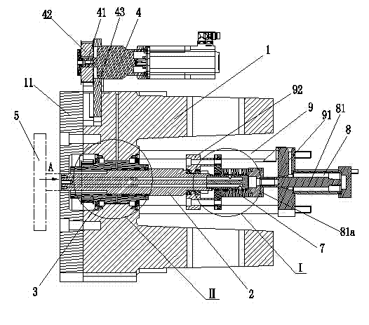
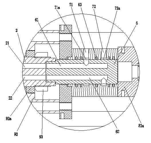
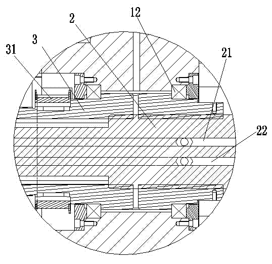
[0026] Such as Figure 1 to Figure 4 Shown is a schematic diagram of the structure of the present invention,

[0027] The reference signs are: movable wall 1, movable wall backing plate 11, bearing 12, linear motion shaft 2, screw hole 2a, water inlet passage 21, water inlet hole 21a, water outlet passage 22, water outlet hole 22a, rotary motion shaft 3. The second synchronous belt wheel 31, the servo motor 4, the output shaft 41, the first synchronous belt wheel 42, the servo motor mounting bracket 43, the mold core 5, the rotating shaft connecting rod 6, the water inlet connection hole 61, the water outlet connection hole 62 , Sealing ring 63, water jacket 7, water inlet 71, annular water inlet 71a, water outlet 72, annular water outlet 72a, drag mold cylinder group 8, drag mold piston rod 81, adapter seat 81a, fixed rod 9, drag mold Cylinder block mount...


PUM


Abstract

The invention discloses a clamping mechanism of an injection molding machine. The clamping mechanism comprises a movable wall and a movable wall backing plate covering the movable wall; a linear motion axis and a rotation motion axis in spline fit are arranged in the movable wall; the rotation motion axis is in rotation connection with a servo motor drive; one end of the linear motion axis is in cooperative connection with a mold rotation core, and the other end is in cooperative connection with a rotating shaft connecting rod; a water jacket sleeves outside the rotating shaft connecting rod; the rear end of the water jacket cooperates with an adapter at the front of a demoulding piston rod controlled by a demoulding cylinder group; the water jacket is provided with a water inlet and a water outlet; the water inlet communicates with a water inlet pathway on the linear motion axis through an annular water inlet groove and a water inlet connection hole on the rotating shaft connecting rod; the water outlet communicates with a water outlet pathway on the linear motion axis through an annular water outlet groove and a water outlet connecting hole on the rotating shaft connecting rod; and the water inlet pathway and the water outlet pathway communicate with the rotation core. The invention has the advantages of reasonable and compact structure, good cooling effect and high machining efficiency.

Description

Technical field [0001] The invention relates to the technical field of injection molding machine manufacturing, in particular to a mold clamping mechanism of an injection molding machine. Background technique [0002] Injection molding machine is a common equipment in injection molding production. Its working principle is to use the thrust of screw or plunger to inject the plasticized plastic in a molten state into a closed mold cavity, and the product is made after solidification and shaping. Injection molding is a cyclic processing process. In the entire injection molding process, the pressure and flow rate of the hydraulic system is a very important factor in determining product quality. [0003] Injection molding machine manufacturing technology is also constantly improving. The injection molding machine has developed from the original single-color single-material injection to the current multi-color multi-component injection; at the same time, the injection molding machine's m...

Claims


Application Information

Patent Timeline
IPC IPC(8): B29C45/64B29C45/73
CPCB29C45/68B29C45/7312
Inventor 王俊杰陈晓周
Owner 富强鑫(宁波)机器制造有限公司
Why Eureka
Try Eureka