Furnace body and installation process of a low-temperature annealing well-type resistance furnace

A pit-type resistance furnace and low-temperature annealing technology, applied in the field of resistance furnace manufacturing, can solve the problems of unevenness and poor thermal insulation performance of the furnace lining, and achieve the effects of reducing heat storage loss, excellent chemical stability, and improving thermal efficiency.

Active Publication Date: 2016-11-23
GUANGXI SHENGLONG METALLURGICAL CO LTD
View PDF8 Cites 0 Cited by
  • Summary
  • Abstract
  • Description
  • Claims
  • Application Information

AI Technical Summary

Problems solved by technology

[0003] At present, the structure of the existing well-type resistance furnace is the same as that of the general well-type furnace. It is composed of a furnace body, a furnace cover, a heating element, a charging basket, a hanger and a temperature control system. The outer shell of the furnace body is welded into a drum shape with steel. , 0.6g / cm3 ultra-light energy-saving refractory bricks are used to build a shaft-type furnace, and the load-bearing parts and parts prone to collision are built with heavy refractory bricks, and an appropriate amount of water glass is mixed into the mud during the masonry to improve the structural strength of the furnace lining. , the insulation layer adopts the composite structure of aluminum silicate refractory well-type resistance furnace fiber, asbestos board, and diatomite insulation brick to improve the insulation performance of the furnace body and reduce the temperature rise of the furnace wall, while only using the composite structure of asbestos board and diatomite insulation brick It is known that the insulation performance of the furnace lining is not very good, and there is still a certain degree of inhomogeneity

Method used


Image

  • Furnace body and installation process of a low-temperature annealing well-type resistance furnace
  • Furnace body and installation process of a low-temperature annealing well-type resistance furnace

Examples


Embodiment Construction

[0020] In order to deepen the understanding of the present invention, the present invention will be further described below in conjunction with the accompanying drawings and embodiments, which are only used to explain the present invention and do not limit the protection scope of the present invention.

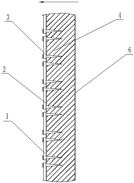
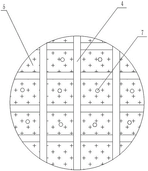
[0021] Such as figure 1 As shown in and 2, a furnace body of a low-temperature annealing well-type resistance furnace, the furnace body includes a furnace shell 6 and a furnace lining 5, the furnace shell 6 is a cylindrical well-shaped structure, and the furnace lining 7 is connected in the furnace shell 6, The furnace shell 6 is supported by reinforced steel 4, the reinforced steel 4 is connected into a well shape, and the furnace lining 5 is a fiber folded block structure, which has low thermal conductivity, low thermal melting, excellent chemical stability, thermal stability, thermal shock resistance, excellent Excellent tensile strength and corrosion resistance. A layer of...


PUM

PropertyMeasurementUnit
thicknessaaaaaaaaaa

Abstract

The invention discloses a furnace body of a low-temperature annealing pit-type resistance furnace and an installation technology thereof. The furnace body comprises a furnace shell and a furnace liner, wherein the furnace shell is a cylindrical pit-type structure, the furnace liner is connected to the furnace shell, reinforcing shape steels are supported in the furnace shell and connected into a grid shape, the furnace linear is a structure of fiber folding blocks, a layer of standard cotton is bonded to the surface of the furnace liner and each furnace liner block is fixedly connected in a grid-shaped frame through an anchor. The furnace body of the low-temperature annealing pit-type resistance furnace has the advantages that the folding fiber block structure of the furnace liner is adopted and the asbestos board structure on the furnace liner is replaced by the standard cotton structure, so that the thermal insulation property of the furnace liner is improved and thermal radiation is reduced; the mounting structure is simple and the process is easy to implement.

Description

technical field [0001] The invention relates to the technical field of resistance furnace manufacturing, in particular to a furnace body of a low-temperature annealing well-type resistance furnace and an installation process thereof. Background technique [0002] The well-type resistance furnace is used for uniform heat treatment of general metal parts at low temperature. It is a conventional annealing treatment equipment with good annealing effect for aluminum alloy cables and relatively energy-saving. [0003] At present, the structure of the existing well-type resistance furnace is the same as that of the general well-type furnace. It is composed of a furnace body, a furnace cover, a heating element, a charging basket, a hanger and a temperature control system. The outer shell of the furnace body is welded into a drum shape with steel. , 0.6g / cm3 ultra-light energy-saving refractory bricks are used to build a shaft-type furnace, and the load-bearing parts and parts prone ...

Claims


Application Information

Patent Timeline
Patent Type & Authority Patents(China)
IPC IPC(8): C21D1/26F27B1/00F27B1/10
CPCC21D1/26F27B1/00F27B1/10
Inventor 傅书根沈卫东戴文卫
Owner GUANGXI SHENGLONG METALLURGICAL CO LTD
Why Eureka
Try Eureka