Displacement and oscillating angle measuring light path structure for two-dimensional holographic scanning exposure workbench

A technology for holographic scanning and measuring optical path, which is applied in the field of holographic scanning exposure two-dimensional table displacement and swing angle measurement optical path structure, which can solve the influence of interference field bearing platform measurement accuracy and the difficulty in processing and assembling Y-axis long reflectors and other problems to achieve the effect of reducing the difficulty of processing and assembly and improving the measurement accuracy

Active Publication Date: 2015-04-15
CHANGCHUN INST OF OPTICS FINE MECHANICS & PHYSICS CHINESE ACAD OF SCI
View PDF7 Cites 11 Cited by
  • Summary
  • Abstract
  • Description
  • Claims
  • Application Information

AI Technical Summary

Problems solved by technology

[0004] The purpose of the present invention is to propose a holographic scanning exposure two-dimensional worktable displacement and swing angle measurement optical path structure, to solve the influence of

Method used


Image

  • Displacement and oscillating angle measuring light path structure for two-dimensional holographic scanning exposure workbench
  • Displacement and oscillating angle measuring light path structure for two-dimensional holographic scanning exposure workbench
  • Displacement and oscillating angle measuring light path structure for two-dimensional holographic scanning exposure workbench

Examples


Embodiment 1

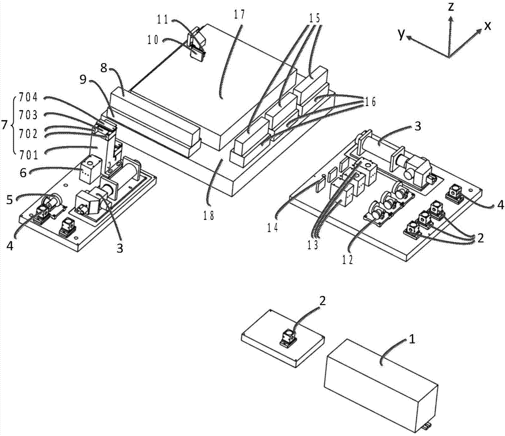
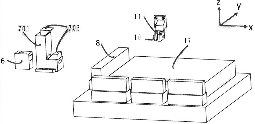
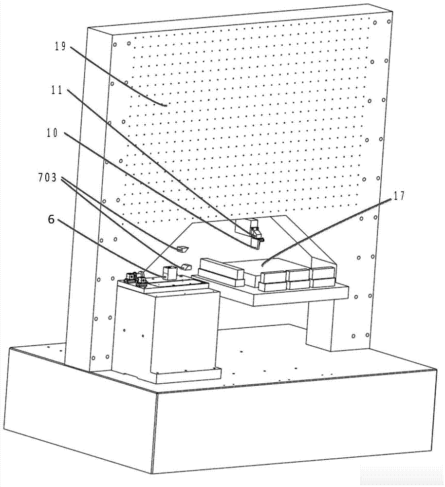
[0034] The method for measuring the displacement of the two-dimensional workbench 18 on the X-axis relative to the interference field is as follows: the laser light emitted by the dual-frequency laser 1 passes through the beam-splitting prism 2, and then enters the X-axis after being reflected by the steering prism 4 The beam direction adjuster 5 then enters the X-axis interferometer 6; after the beam passes through the X-axis interferometer 6, it is divided into two clusters of light up and down; the cluster of light on the top passes through the two periscope structures 7 to carry out the optical path After refraction, it is incident on the surface of the X-axis reference mirror 10, and then returns to the inside of the biaxial interferometer along the original optical path; a cluster of light located at the bottom of the X-axis interferometer 6 is reflected by the X-axis measurement After being reflected by the mirror 8, it returns to the interior of the X-axis interferomete...


PUM


Abstract

The invention discloses a displacement and oscillating angle measuring light path structure for a two-dimensional holographic scanning exposure workbench, belongs to the field of manufacturing of holographic planar diffraction gratings, and aims to solve the problems of influence on the measurement accuracy caused by thermal expansion of an interference field carrying platform and high difficulty in processing and adjustment of a Y-axis long-strip reflecting mirror with the meter-scale size in the prior art. The displacement and oscillating angle measuring light path structure for the two-dimensional holographic scanning exposure workbench comprises an X-axis measurement system and a Y-axis measurement system, wherein the X-axis measurement system comprises an X-axis light beam direction adjuster, an X-axis interferometer, a periscope structure, an X-axis measurement reflecting mirror and an X-axis reference reflecting mirror; the Y-axis measurement system comprises a plurality of Y-axis interferometers, a Y-axis reference reflecting mirror and a Y-axis measurement reflecting mirror; laser light emitted by a double-frequency laser is split into two beams of light through a beam splitting prism, and the two beams of light enter the X-axis measurement system and the Y-axis measurement system through a steering prism respectively; the X-axis interferometer in the X-axis measurement system is used for realizing the measurement of the relative position of the X axis of the workbench through the periscope structure; the Y-axis measurement system is used for realizing the measurement of the relative position of the Y axis through the Y-axis interferometers.

Description

technical field [0001] The invention belongs to the technical field of making holographic plane diffraction gratings, and in particular relates to a holographic scanning exposure two-dimensional workbench displacement and swing angle measurement optical path structure. Background technique [0002] There are two main methods for manufacturing meter-scale holographic gratings: one is the static interference field exposure method, in which two planar Gaussian beams are superimposed to form linear interference fringes, and the interference field and the grating substrate are always kept stationary, one exposure will interfere The fringes are recorded on the exposure glue, and the same or even larger interference field is required to fabricate meter-scale gratings. The other is the scanning exposure method, which uses two small-section Gaussian lasers to interfere with each other to form interference fringes (also known as interference fields) with a spot diameter of millimeters...

Claims


Application Information

Patent Timeline
IPC IPC(8): G01B11/02G01B11/26
Inventor 李晓天刘兆武于海利唐玉国巴音贺希格齐向东李文昊白志红
Owner CHANGCHUN INST OF OPTICS FINE MECHANICS & PHYSICS CHINESE ACAD OF SCI
Why Eureka
Try Eureka