
High power spatial filter

A technology of light and light beams, applied in the field of optical systems

Active Publication Date: 2015-04-15
IPG PHOTONICS CORP
View PDF8 Cites 8 Cited by
  • Summary
  • Abstract
  • Description
  • Claims
  • Application Information

AI Technical Summary

Problems solved by technology

In many cases, the coupling of light propagating into the fiber also has the same problems as described above for the pump light delivery system

Method used


Image

  • High power spatial filter
  • High power spatial filter
  • High power spatial filter

Examples


Embodiment Construction

[0024] Embodiments of the present invention will be described in detail below. Wherever possible, the same or similar reference numerals are used in the drawings and the description to refer to the same or similar components or steps. The drawings are in simplified form and not to exact scale. Directional (up and down, etc.) or motion (forward / backward) terms are used with respect to the figures for convenience and clarity only. These similar directional terms should not be construed as limiting the scope of the invention in any way.

[0025] Optical fibers are flexible, transparent fibers made of glass-silicon not much thicker than a human hair. An optical fiber typically includes a transparent core surrounded by a transparent cladding material having a smaller refractive index. Light is kept in the core by total internal reflection. A fiber with multiple cores supporting many transverse propagation paths is called a multimode (MM) fiber, while a fiber with a core support...


PUM


Abstract

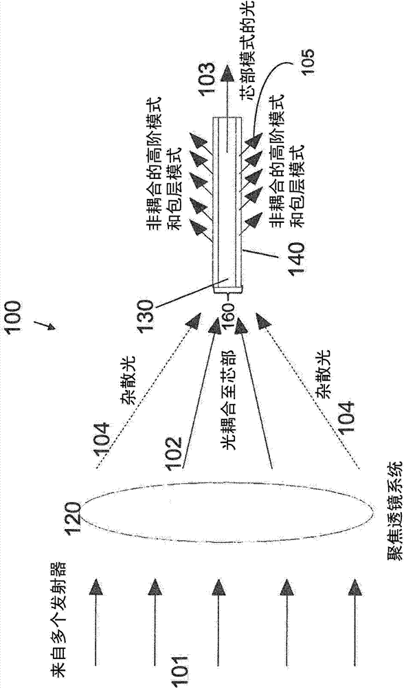
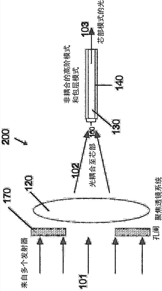
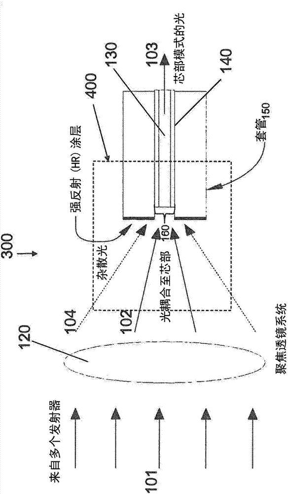
An improved high power special filter, system and method. In the system, an optical fiber is disposed inside a ferule channel structure, and the channel structure is aligned with a focusing lens system. The end of the fiber is at a distance D from the channel opening that faces the focusing lens system, and D is determined by the system's numeric aperture factor and the cladding thickness of the optical fiber.

Description

technical field [0001] The present invention relates to an optical system that operates to filter out high numerical aperture or numerical aperture rays from laser light propagating through free space. Background technique [0002] Lasers, generally including solid-state lasers and fiber lasers, are becoming more and more efficient in order to meet today's industrial demands. In general, however, high light energies should be obtained without degrading the quality of the laser light. Laser propagation through free space is often encountered in fiber laser systems of various configurations or configurations. For example, pigtailed optical components of fiber laser systems, such as isolators, circulators, etc., are configured with optical path continuities that require light to propagate through free space. Yet another optical configuration that requires light to propagate through free space includes a laser diode module that typically operates as a pump source. A laser dio...

Claims


Application Information

Patent Timeline
Patent Type & Authority Applications(China)
IPC IPC(8): H01S3/10G02B5/20
CPCH01S3/09415H01S3/094003G02B27/46G02B6/3813G02B6/4296G02B6/262G02B6/32G02B6/14
Inventor 伊格尔·贝尔谢夫瓦迪姆·丘亚诺夫阿列克谢·科米萨诺夫尼古拉·什特夫
Owner IPG PHOTONICS CORP
Learn More