Electric melting forming method of nuclear power conventional island low-voltage rotor

A low-pressure rotor and conventional island technology, applied in welding equipment, metal processing equipment, manufacturing tools, etc., can solve the problems of uneven material phase structure, difficult control of chemical and mechanical properties, complicated operation, etc., and achieve corrosion resistance and other properties Highlight, shorten the product cycle, simplify the effect of processing procedures

Active Publication Date: 2015-04-22
NANFANG ADDITIVE MFG TECH
View PDF5 Cites 8 Cited by
  • Summary
  • Abstract
  • Description
  • Claims
  • Application Information

AI Technical Summary

Problems solved by technology

Although this process is used to produce the rotor steel material without exception, due to the complex operation (including rotor steel material research and development, pure steel smelting research and development, forging process research and development, heat treatment process research and development, etc.), the control of chemical and mechanical properties is difficult. , resulting in inhomogeneous material phase structure and even stress cracking during heat treatment
In addition, the utilization rate of forged structural materials is low and the cycle is long, which also leads to relatively high manufacturing costs and low efficiency; and due to my country's own technical level, the quality stability of the manufactured material components is poor, and the scrap rate is high, resulting in serious delays in the project. cause great waste

Method used


Image

  • Electric melting forming method of nuclear power conventional island low-voltage rotor
  • Electric melting forming method of nuclear power conventional island low-voltage rotor
  • Electric melting forming method of nuclear power conventional island low-voltage rotor

Examples


Embodiment Construction

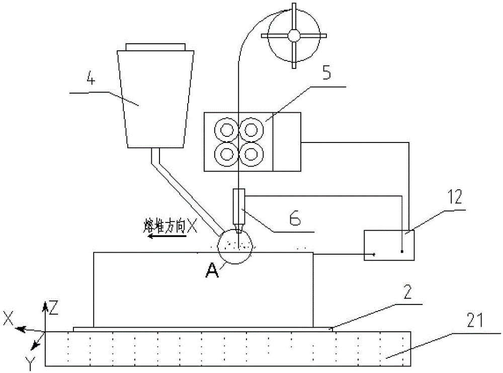
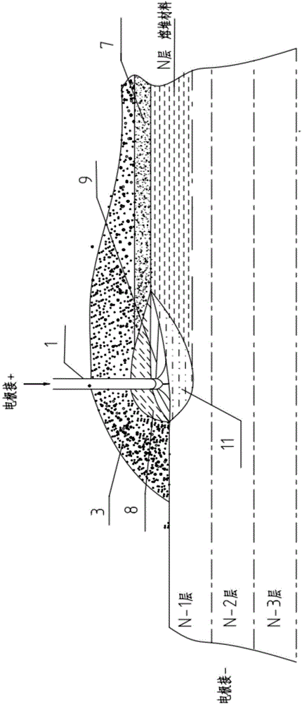
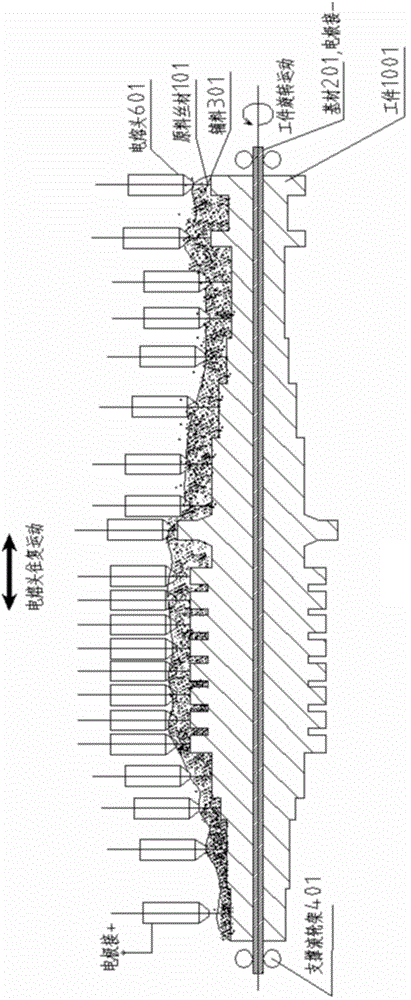
[0017] Specific embodiments of the present invention will be described below with reference to the accompanying drawings. Figure 1A It is a schematic diagram for illustrating the electrofusion forming method in the specific embodiment; Figure 1B for Figure 1A Partial enlarged view near the location shown in A. Since it is a schematic diagram, the components in the diagram are schematic, and their actual shapes and dimensions are not limited by the diagram.

[0018] In this forming method, the raw wire material 1 is melted and deposited layer by layer (shown in FIG. 1 as the state when the Nth layer is deposited) on the base material 2, thereby finally forming a desired metal member.

[0019] The specific implementation process is:

[0020] A. The wire feeding mechanism 5 sends the raw material wire 1 to the surface of the base material 2 placed on the workbench 21 , which is covered with the granular auxiliary materials conveyed by the powder feeding mechanism 4 .

[0021...


PUM

PropertyMeasurementUnit
diameteraaaaaaaaaa
surface temperatureaaaaaaaaaa
lengthaaaaaaaaaa

Abstract

The invention provides an electric melting forming method of a nuclear power conventional island low-voltage rotor, which has high efficiency, low cost and excellent mechanical performance. The method comprises the following steps: an electric melting head and a substrate are connected to two poles of a power supply; a raw metal wire is sent to the surface of the substrate by a conveying mechanism and the electric melting head; under the stacking protection of particle accessories, an electric arc is generated between the raw metal wire and the substrate for melting the accessories to form a molten slag pool; the raw metal wire is molten under the effect of three thermal compounding high-energy heat sources of electric arc heat, resistance heat and electroslag heat to form a molten pool; the raw metal wire and the accessories are continuously conveyed; the relative movement of the electric melting head and the substrate is controlled; quick cooling and layer-by-layer solidification and accumulation of the molten pool on the substrate are realized; finally, the nuclear power conventional island low-voltage rotor is formed through layer-by-layer accumulation; the rotor adopts a 30 Cr2Ni4MoV material; the raw metal wire prepared through electric melting contains 0.20-0.28% of C; the material prepared through electric melting contains 0.10-0.18% of C; and the grain size is 7-10 grade.

Description

technical field [0001] The invention relates to an electrofusion forming method for a nuclear power conventional island low-voltage rotor. Background technique [0002] The 30Cr2Ni4MoV material has the advantages of high hardenability, good comprehensive mechanical properties, and good thermal processing technology, so it is widely used in the production of low-pressure rotors for nuclear power steam turbines. However, this kind of steel is essentially coarse-grained steel, which has strong genetic characteristics, and is prone to coarse grains and mixed crystals, which has caused great difficulties in material manufacturing. [0003] At present, the preparation of rotor steel materials is mainly realized by smelting and casting steel ingots, forging and forming, and then multiple times of normalizing heat treatment. This process refines the grains and obtains material components with good plastic toughness mechanical properties and high temperature properties. In actual pr...

Claims


Application Information

Patent Timeline
Patent Type & Authority Applications(China)
IPC IPC(8): B23K28/02
CPCB23K28/02
Inventor 不公告发明人
Owner NANFANG ADDITIVE MFG TECH
Why Eureka
Try Eureka