Self-driven liquid metal machine and application thereof

A liquid metal, self-driven technology, applied in the direction of micro-manipulators, manipulators, manufacturing tools, etc., can solve the problems of increasing machine size, short motion life, low absolute motion speed, etc., to achieve expanded application range, simple and easy design, and broad The effect of applying the foreground

Active Publication Date: 2015-04-22
TSINGHUA UNIV
View PDF4 Cites 18 Cited by
  • Summary
  • Abstract
  • Description
  • Claims
  • Application Information

AI Technical Summary

Problems solved by technology

Increasing the size of micro-machines at the micro-nano scale to the order of millimeters/centimeters can effectively solve the problems of short motion life and low absolute motion speed.
However, increasing the size of the machine necessitates an increase in its driving force
Many studies use external energy supply meth...

Method used


Image

  • Self-driven liquid metal machine and application thereof
  • Self-driven liquid metal machine and application thereof
  • Self-driven liquid metal machine and application thereof

Examples


Embodiment 1

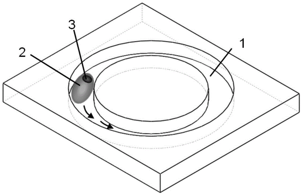
[0026] Such as figure 1 As shown, this embodiment is described by taking the self-propelled liquid metal machine in the annular channel to automatically drive its own movement as an example.

[0027] 1. Prepare the aqueous solution 1 with a specific concentration, raise the temperature of the aqueous solution 1 water bath to 60°C to speed up the opening of the liquid metal drive, and then inject it into the annular channel.

[0028] 2. Use a syringe to inject a certain amount of liquid metal material 2 into the annular channel, then use tweezers to grab a small piece of aluminum sheet 3 and place it in the aqueous solution 1, and put the aluminum sheet 3 in contact with the liquid metal material 2, so that the aluminum sheet 3 Perform electrochemical corrosion reaction with aqueous solution 1. After contacting for a certain period of time, the aluminum sheet 3 is adsorbed on the liquid metal material 2, and the reaction speed is accelerated. With the acceleration of the react...

Embodiment 2

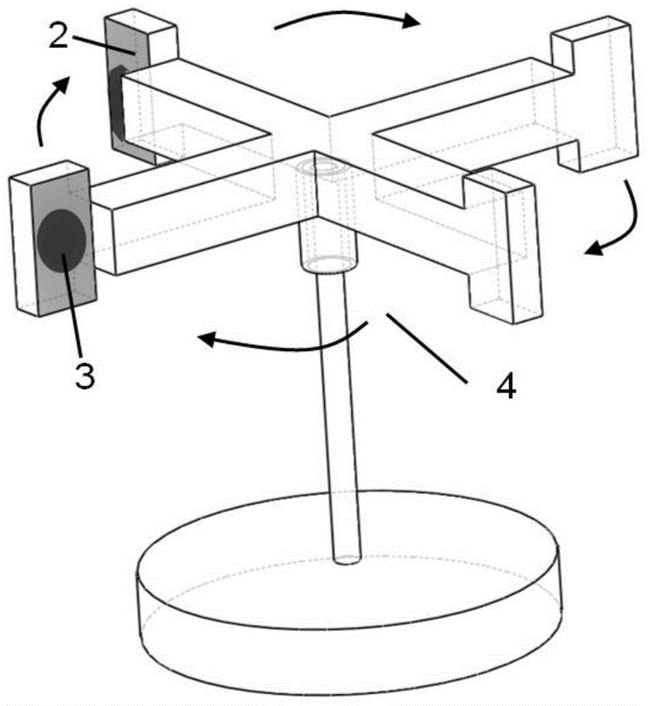
[0030] Such as figure 2 As shown, this embodiment is described by taking the self-propelled liquid metal machine liquid metal to drive the movement of the small horizontal rotor 4 as an example.

[0031] 1. Prepare the aqueous solution 1 with a specific concentration, raise the temperature of the aqueous solution 1 to about 60°C in a water bath, and then pour the aqueous solution 1 into the container.

[0032] 2. Place the small horizontal rotor 4 in the container.

[0033]3. A certain amount of liquid metal material 2 is added dropwise on the copper sheet attached to the horizontal rotor 4, and the liquid metal adheres to the copper sheet after a few minutes by utilizing the corrosion characteristics of the liquid metal.

[0034] 4. Use tweezers to pick up a small piece of aluminum sheet 3, and put the aluminum sheet 3 in contact with the liquid metal material 2. Under the joint action of the aqueous solution 1 and the liquid metal material 2, the aluminum sheet 3 begins to...

Embodiment 3

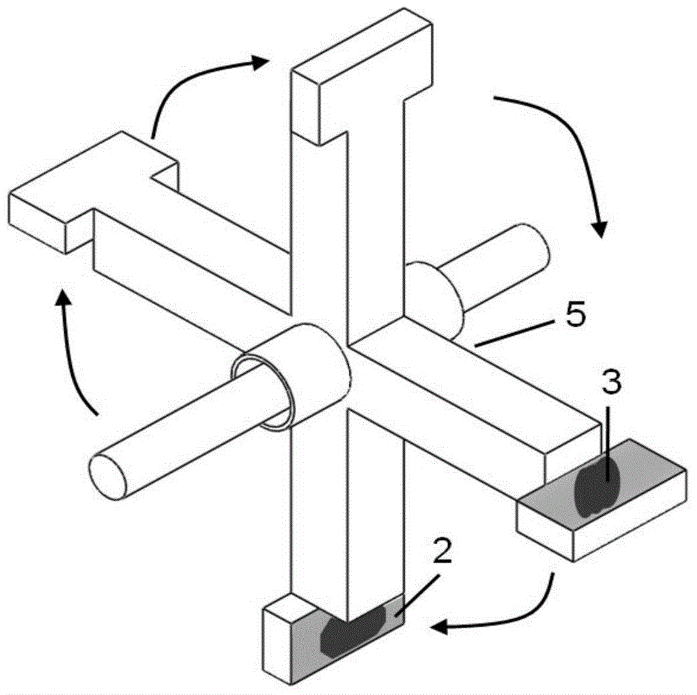
[0036] Such as image 3 As shown, this embodiment is described by taking the self-propelled liquid metal machine as an example to drive the small vertical rotor 5 to move.

[0037] 1. Prepare an aqueous solution with a specific concentration, raise the temperature of the aqueous solution water bath to about 60°C, then pour the solution 2 into the container, and place the small vertical rotor 5 in the container.

[0038] 2. A certain amount of liquid metal material 2 is added dropwise on the copper sheet attached to the rotor, and the liquid metal material 2 adheres to the copper sheet after a few minutes by utilizing the corrosion characteristics of liquid metal.

[0039] 3. Use tweezers to pick up a small piece of aluminum sheet 3, and put the aluminum sheet 3 in contact with the liquid metal material 2. Under the joint action of the aqueous solution 1 and the liquid metal material 2, the aluminum sheet 3 begins to undergo a chemical reaction, generating bubbles, and Drive t...


PUM


Abstract

Provided are a self-driven liquid metal machine and the application of the self-driven liquid metal machine. Liquid metal of gallium or gallium and indium alloy or gallium, indium and tin alloy or gallium, indium, tin and zinc alloy is dropwise added to a strong electrolyte ion solution like a NaOH solution, an HC1 solution, a Na2CO3 solution and a NaC1 solution at specific temperature and concentration; an aluminum sheet adheres to the liquid metal for chemical reaction and electrochemical corrosion, bubbles are generated, and chemical energy is released and converted into kinetic energy so as to drive the liquid metal to move, wherein the driving force can make the liquid metal to move automatically instead of intervention of external energy, can drive small-size rotors or other things to move, and can also convey liquid to provide power for small-size pumps or small-size blenders, so that the machine is driven without replying on external energy, machine design is greatly simplified, the gap that energy is supplied automatically to drive objects to move is filled in, and the machine has wide application prospects. The self-driven liquid metal machine can greatly promote progress of the design of flexible robots and flexible drive machines, the micro-channel chip technology and the like.

Description

technical field [0001] The invention relates to the technical field of automatically supplying energy to drive motion, in particular to a self-driven liquid metal machine and its application. Background technique [0002] Self-driving micromachines have broad and attractive application prospects, and they do not need external energy supply to complete their tasks. Such micromachines, also known as micromotors or microrobots, are being widely studied, and they play an extremely important role in applications such as drug delivery, environmental governance, and ion detection. Among them, the biological motor synthesizes biological energy storage units such as ATP through the ingested food, and then uses the energy generated by the spontaneous decomposition of the energy storage unit to maintain its own movement. This efficient energy conversion mode has inspired people to design and manufacture artificially synthesized self-driving machines. Nowadays, various artificially sy...

Claims


Application Information

Patent Timeline
IPC IPC(8): B25J13/00B25J7/00
Inventor 张洁姚又友刘静
Owner TSINGHUA UNIV
Why Eureka
Try Eureka