An in-situ treatment and purification device for polluted water

An in-situ treatment and purification device technology, which is applied in the field of water pollution treatment, can solve problems such as difficulty in adaptation, inability to meet economic and high efficiency at the same time, and achieve the effects of improving purification efficiency, improving biochemical reaction environment, and inhibiting algae growth

Active Publication Date: 2016-07-06
WUHAN ZHONGKE HYDROBOLOGY ENVIRONMENTAL ENG
View PDF6 Cites 2 Cited by
  • Summary
  • Abstract
  • Description
  • Claims
  • Application Information

AI Technical Summary

Problems solved by technology

For the in-situ treatment and purification of water pollution in rivers and lakes, different from sewage treatment, it is required to have comprehensive advantages such as high efficiency, economy, convenient management, stable treatment effect, and good mobility. However, there are various in-situ treatment and purification technologies for water pollution , all have certain limitations, especially the two key indicators of economy and efficiency cannot be met at the same time, and it is difficult to adapt to the current pollution control of rivers and lakes in our country

Method used


Image

  • An in-situ treatment and purification device for polluted water
  • An in-situ treatment and purification device for polluted water
  • An in-situ treatment and purification device for polluted water

Examples


Embodiment 1

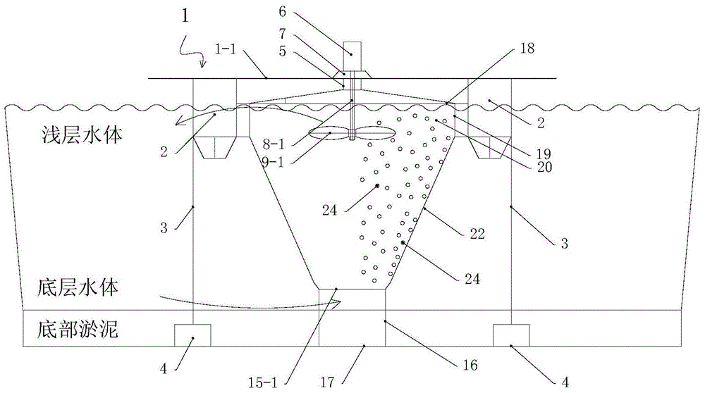
[0044] Such as figure 1 shown.

[0045] An in-situ treatment and purification device for polluted water, comprising: a device frame floating platform 1 floating on the surface of the water body, a platform support 5 arranged below the device frame floating platform 1, a process under the platform support 5 and located in the water body The water grid cylinder 19, the bottom of the water grid cylinder 19 communicates with the isolation outer cylinder 22, the bottom of the isolation outer cylinder 22 is provided with a porous sieve plate 15-1, the bottom of the isolation outer cylinder 22 communicates with the water inlet grid cylinder 16, and the isolation outer cylinder 22 It is filled with suspension filler 24 .

[0046] The device frame floating platform 1 includes a platform 1-1, the bottom of the platform 1-1 is provided with a floating body 2, the platform 1-1 is also connected with a fixed anchor block 3 through a fixed cable 4, and the bottom of the platform 1-1 is als...

Embodiment 2

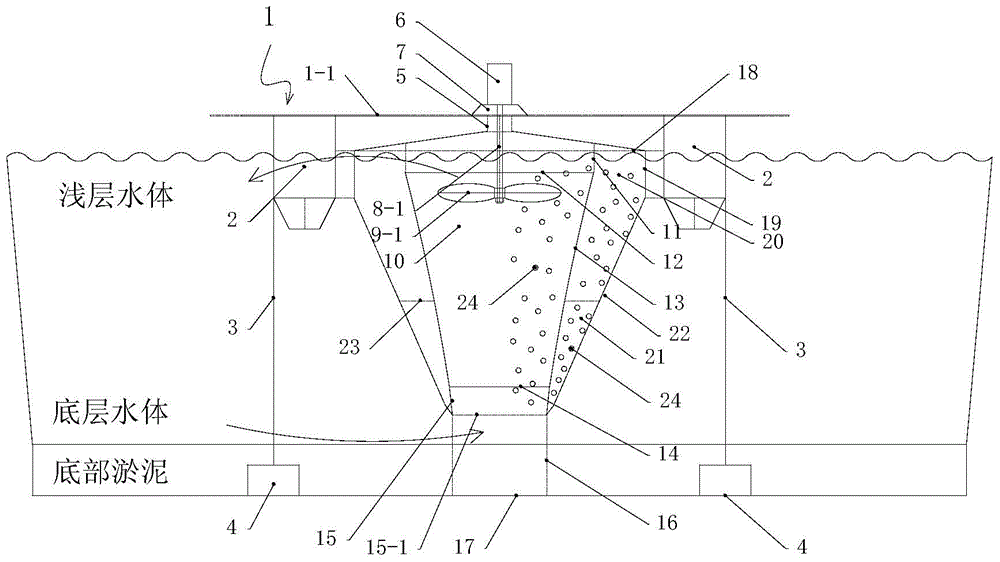
[0053] Such as Figure 2-1~Figure 2-2 As shown, on the basis of embodiment 1, embodiment 2 also includes the following components:

[0054] 11. Fixing parts; 12. Upper supporting ring; 13. Diversion cylinder; 14. Lower supporting ring; 15. Supporting ring seat;

[0055] An in-situ treatment and purification device for polluted water, further comprising a diversion cylinder 13 arranged in the isolation outer cylinder 22, an upper support ring 12 is arranged on the upper part of the diversion cylinder 13, and a claw-shaped cantilever passes through the fixing part 11 and the upper support ring 12 connection, the bottom of the diversion cylinder 13 is provided with a lower support ring 14, the outside of the diversion cylinder 13 is connected to the inner side of the diversion cylinder 13 through the inner and outer cylinder support frame 23, and the lower support ring 14 is connected with the porous sieve plate 15 The support ring seat 15 on -1 is connected. The upper edge of ...

Embodiment 3

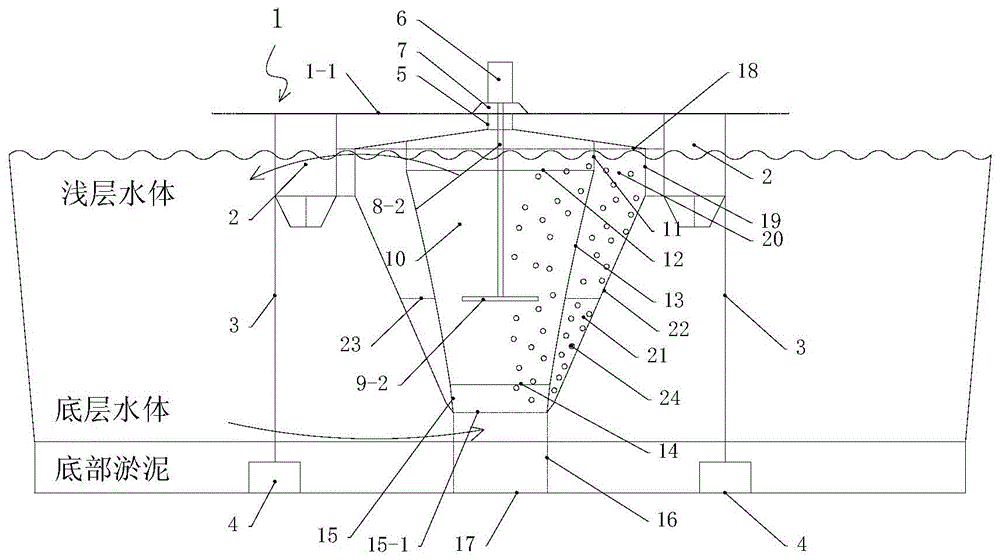
[0060] Such as diagram 2-1 Shown, embodiment 3 also includes on the basis of embodiment 2:

[0061] 5. Platform support; 6. Power device; 7. Support; 8-1. Transmission shaft; 9-1. Blade.

[0062] An in-situ treatment and purification device for polluted water, the water flow lifting device includes a power device 6 arranged on a platform 1-1, the power device 6 is an electric motor, and the power device 6 is driven by a transmission shaft rod 8-1 and located in the guide Paddle 9-1 in cylinder 10.

[0063] The paddle 9 rotates and generates a rotary thrust upwards to act on the water body, pushing the water existing in the upper part of the diversion inner cylinder 10 upwards. Due to the continuity of the water body, the water inlet grid tube 16 at the bottom of the diversion inner cylinder 10 is continuously sucked. Water entering the external bottom water body, the bottom water body is lifted to the water surface from bottom to top, gushes out from the upper outlet of the...


PUM


Abstract

The invention relates to the field of water pollution treatment, and discloses an in-situ treatment and purification device for polluted water, which includes a floating platform of a device frame, a platform support, and a water grid cylinder. The bottom is provided with a porous sieve plate, the bottom of the isolation outer cylinder is connected with the water inlet grid cylinder, and the isolation outer cylinder is filled with suspended fillers. A water flow lifting device into the water. The present invention can adopt single cylinder or double cylinder structure. And can utilize wind power or solar energy or both to convert into electric energy function, also can directly adopt wind power.

Description

technical field [0001] The invention relates to the field of water pollution control, in particular to an in-situ treatment and purification device for polluted water bodies, which is suitable for polluted water bodies, such as semi-closed stagnant rivers, river reservoirs, Haikou harbors, closed non-flowing lakes, reservoirs, In-situ treatment of eutrophication polluted water bodies such as ponds and artificial landscape water bodies. Background technique [0002] With the acceleration of urbanization and industrialization in our country, on the one hand, the demand gap for water resources is increasing day by day; Nitrogen and phosphorus nutrients are discharged into natural water bodies, causing eutrophication of water quality in many rivers and lakes. Therefore, how to control the water pollution of these rivers and lakes and realize the sustainable utilization of water resources is an urgent problem to be solved in order to realize the sustainable development of our co...

Claims


Application Information

Patent Timeline
Patent Type & Authority Patents(China)
IPC IPC(8): C02F3/08
CPCC02F3/087C02F2103/007Y02W10/10Y02W10/33Y02W10/37
Inventor 王雷陈文峰童莉刘旻
Owner WUHAN ZHONGKE HYDROBOLOGY ENVIRONMENTAL ENG
Why Eureka
Try Eureka