
Double-piston-rotor internal combustion engine

A rotor internal combustion engine, double piston technology, applied in the direction of internal combustion piston engines, combustion engines, mechanical equipment, etc., can solve the problems of low output torque, high maintenance costs, large space occupation, etc., achieve low vibration and noise levels, long service life The effect of long length and large power output torque

Active Publication Date: 2015-04-22
创历电器(滁州)股份有限公司
View PDF6 Cites 8 Cited by
  • Summary
  • Abstract
  • Description
  • Claims
  • Application Information

AI Technical Summary

Problems solved by technology

[0006] 2. During the operation of the crankshaft-connecting rod internal combustion engine, the direction of the force acting on the piston by the connecting rod changes periodically, and when the engine power output is maximum, the force acting on the piston by the connecting rod also reaches the maximum value along the normal direction of the cylinder wall , resulting in a large frictional power loss between the piston and the cylinder, and it is easy to cause damage to the surface between the piston and the cylinder due to friction
[0007] 3. During the operation of the crankshaft-connecting-rod internal combustion engine, the piston is always in a state of reciprocating motion. When intake air, the piston quickly enters the compression stroke at the bottom dead center, so that there is no more time to absorb when the cylinder volume is the largest. More fresh mixed oil and gas are fed in, and the piston quickly enters the intake stroke when it reaches the top dead center when exhausting, so that there is no more time for the exhaust gas to be discharged to the maximum extent when the cylinder volume is the smallest. These conditions will eventually affect more Too much fresh mixed oil and gas enters the cylinder, which leads to low engine ventilation efficiency and affects the increase of engine power per liter to a certain extent.
[0008] 4. The crankshaft connecting rod mechanism is not an axisymmetric part, and the vibration and noise caused by the crankshaft connecting rod mechanism during the operation of the internal combustion engine are large; the crankshaft connecting rod mechanism is difficult to balance, and its manufacturing process is complicated and the cost is high; , crankshaft connecting rod mechanism, etc. are easy to wear, and the maintenance cost is high; the limit speed of the internal combustion engine using the crankshaft connecting rod is low, which seriously restricts the improvement of the power-to-weight ratio of the engine
[0009] 5. The throttle valve, crankshaft connecting rod and other structures of the crankshaft connecting rod internal combustion engine are complex and take up a lot of space, resulting in the engine structure not being compact enough
[0018] 1. After several design improvements, the crankshaft-connecting rod internal combustion engine has basically reached its technical performance limit, and its technical performance indicators such as power-to-weight ratio, fuel consumption rate, manufacturing processability, and service life are difficult to meet higher requirements;
[0019] 2. The triangular rotor engine is a breakthrough in internal combustion engine technology, but its technical weaknesses such as high fuel consumption, low output torque, and difficult sealing make it difficult to become the main body of the new generation of internal combustion engine technology;
But so far, among such invention patents, some patents are variants of the crankshaft-connecting rod internal combustion engine, which still retain the crankshaft connecting rod-shaped parts in its structure, which affects the performance of the internal combustion engine; some patents have too complicated structural design , affecting the power-to-weight ratio, manufacturing process, service life of the internal combustion engine, etc.; some patents lack the necessary quantitative design and analysis, and the products designed and manufactured according to their plans actually do not meet the technical performance of the patent nominal

Method used


Image

  • Double-piston-rotor internal combustion engine
  • Double-piston-rotor internal combustion engine
  • Double-piston-rotor internal combustion engine

Examples


Embodiment 1

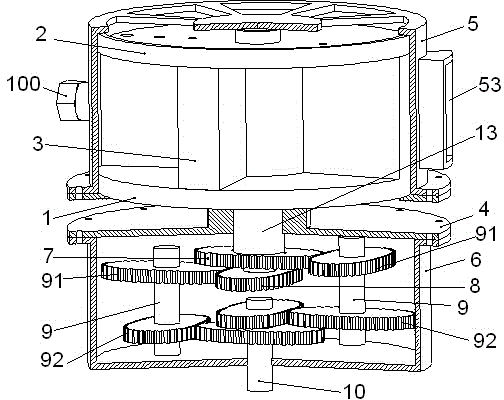
[0093] Example 1: The first technical solution of the present invention, the dual-piston rotor internal combustion engine, includes a combustion system, a transmission system, etc., see Figure 1 to Figure 14 ,as well as Figure 20 to Figure 29 .

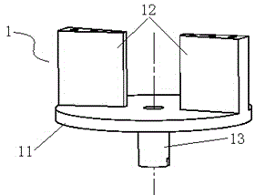
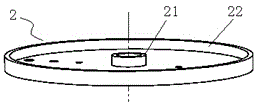
[0094] The first rotor 1 is a Y-shaped part, including a rotating shaft disk 11. One end of the rotating shaft disk 11 is two first piston bodies 12 symmetrical to the axis of the first rotating shaft 13, and the other end is provided with the first rotating shaft 13. The end of the rotating shaft 13 is provided with a keyway, the axis of the first rotating shaft 13 is provided with a shaft hole, the cover plate 2 is in the shape of a garden disc, and the cover plate 2 is also provided with some through holes corresponding to the position on the first piston body 12, The first rotor 1 and the cover plate 2 are connected and fixed by several bolts passing through the through holes of the first piston body 12 and the cover plate 2 ...

Embodiment 2

[0107] Example 2: In Embodiment 1 of the present invention, the disc-shaped member 4 can cancel the upper end disc 41 in a network structure, and retain the lower end disc 42 of the disc-shaped member 4, as well as the shaft hole provided in the middle of the lower end disc 42 and the screw holes provided around the disc surface. , so that the disk-shaped member 4 has only a single-layer disk surface. That is: the disk-shaped member 4 can be a single-layer disk surface, with a shaft hole in the middle, and screw holes on the periphery of the disk surface. The flange plate of the combustion chamber housing 5, the disc-shaped member 4 and the flange plate of the gear box 6 are fixedly connected by bolts in sequence. Others are the same as in Example 1.

Embodiment 3

[0108] Example 3: The second technical solution of the present invention, a double-piston rotor internal combustion engine, includes a combustion system, a transmission system, etc., see Figure 15 to Figure 19 .

[0109] The first rotor a1' is a Y-shaped part, one end of which is two first piston bodies a12' symmetrical to the axis of the first rotary shaft a13', and the other end is provided with a keyway. The first rotary shaft a13' of the first rotor a1' The axis is provided with a circular through hole. The second rotor a2' is a T-shaped piece, one end of which is two second piston bodies a22' that are symmetrical to the axis of the second rotary shaft a21', and the other end is provided with a keyway; the second rotary shaft a21' is sleeved on the first rotor a1' in the circular through hole. The fan angle of the first piston body a12' and the second piston body a22' are equal to the outer diameter. A circular through hole is opened in the center of the disc a4', ...


PUM


Abstract

The invention discloses a double-piston-rotor internal combustion engine. A first rotor comprises a rotating shaft disc, two first piston bodies are arranged at one end of the rotating shaft disc, a first rotating shaft provided with a first egg-shaped gear is installed at the other end of the rotating shaft disc, and the bottom face of a cover plate is connected with the end faces of the first piston bodies. A second rotor comprises a second rotating shaft, two second piston bodies are arranged at one end of the second rotating shaft, a second egg-shaped gear is installed at the other end of the second rotating shaft, the second rotating shaft is installed in a shaft hole of the first rotating shaft in a penetrating mode, and the second rotating shaft and the first rotating shaft are jointly installed in a shaft hole of a disc-shaped piece in a penetrating mode. An upper end disc and a lower end disc of the disc-shaped piece are connected with a combustor shell and a flange of a gearbox through bolts respectively. A power output gear shaft is installed in a shaft hole in the bottom of the gearbox. Upper egg-shaped gears of two double-egg-shaped gear shafts are meshed with the first egg-shaped gear and the second egg-shaped gear respectively, and lower egg-shaped gears of the two double-egg-shaped gear shafts are meshed with two egg-shaped gears on the power output gear shaft respectively. The double-piston-rotor internal combustion engine is low in oil consumption, high in power-to-weight ratio, large in output torque, low in vibration, simple and compact in structure, easy to design and good in manufacturability.

Description

technical field [0001] The invention relates to the technical field of internal combustion engines, in particular to rotary piston internal combustion engines. Background technique [0002] A heat engine is a device that converts heat energy into mechanical energy. The internal combustion engine is an important type of heat engine. The internal combustion engine mainly includes an ignition system, a combustion system, a transmission system, a cooling system, an oil supply system, and a lubrication system. [0003] Since the invention of the crankshaft-connecting-rod internal combustion engine around 1898 AD, the crankshaft-connecting-rod internal combustion engine has been widely used in ground vehicles, shipping and various power equipment, and has greatly accelerated the progress of human history. The basic working principle of the crankshaft-connecting rod internal combustion engine is that the piston is pushed up and down by the high-pressure combustion gas in the cylind...

Claims


Application Information

Patent Timeline
Patent Type & Authority Applications(China)
IPC IPC(8): F02B53/00F02B53/14F02B55/02F02B55/14
CPCY02T10/12
Inventor 唐仁杰熊薇
Owner 创历电器(滁州)股份有限公司
Learn More