
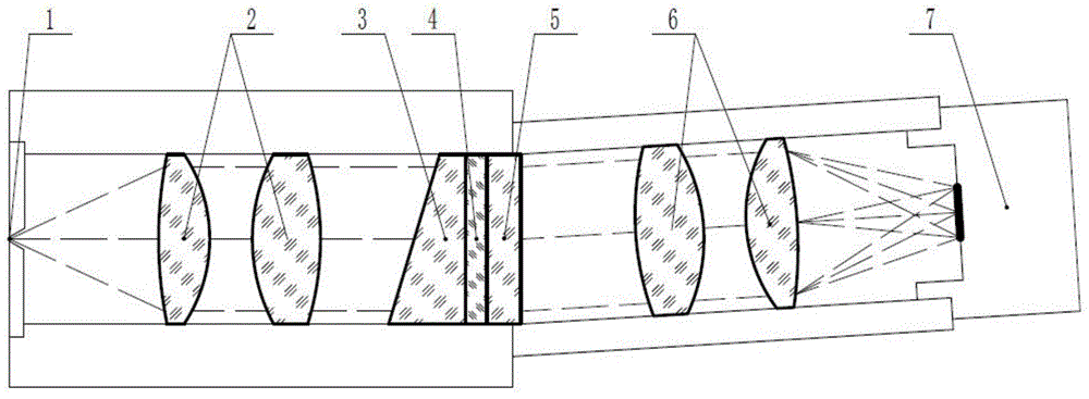
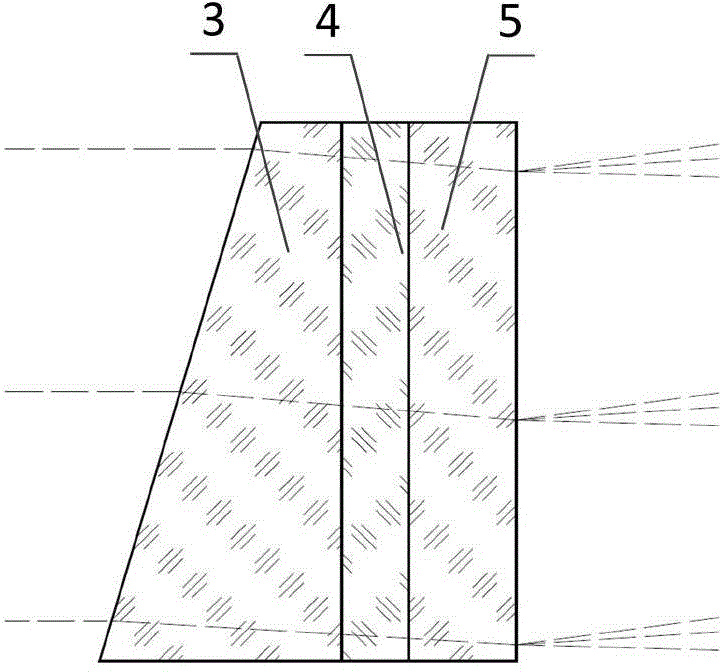
Light path structure of prism-grating imaging spectrometer

A grating imaging and spectrometer technology, applied in the field of imaging spectroscopy, can solve problems such as large spectral line distortion, and achieve the effects of superior correction, reduced difficulty, and superior spectral line distortion.

Inactive Publication Date: 2015-04-22
CHANGCHUN INST OF OPTICS FINE MECHANICS & PHYSICS CHINESE ACAD OF SCI
View PDF3 Cites 7 Cited by
  • Summary
  • Abstract
  • Description
  • Claims
  • Application Information

AI Technical Summary

Problems solved by technology

[0005] In order to solve the technical problems of large spectral line distortion and unique grating selection in the prior art, the present invention proposes an optical path structure of a prism-grating imaging spectrometer to further improve the optical performance of this type of imaging spectrometer, mainly the spectral line Distortion correction, while optimizing the core light-splitting components, get rid of the uniqueness of grating selection

Method used


Image

  • Light path structure of prism-grating imaging spectrometer
  • Light path structure of prism-grating imaging spectrometer

Examples


Embodiment 1

[0022] In the optical path of the present invention: the working band of the imaging spectrometer is 400-800nm, and the center wavelength is selected as 633nm; the incident slit 1 is long 14mm, F # is 2.4; the imaging objective lens 6 adopts a six-piece lens group structure (the collimating objective lens is an inverted structure), the focal length is 54.1mm, and the field of view is 8.5°; the prism apex angle is 10.42°, and the thickness is 5mm; Holographic transmission grating, substrate and protective glass material are B270, the thickness is 1mm, the grating line density is 300l / mm, the diffraction order is +1; the area array detector 7 is B1920 detector of IMPERX company, the resolution is 1920 ×1080 pixels, the pixel size is 7.4μm×7.4μm.

[0023] Through optical software for ray tracing, the optical axis of the rear-end imaging objective lens deflects 3.58° along the dispersion direction, and has good imaging quality in the entire spectral range. At 400nm, 633nm, and 800...

Embodiment 2

[0025] Under the condition that the optical result designed in Example 1 remains unchanged, only the grating is changed to a ruled transmission grating (grating parameters: the base material is B270, the thickness is 3mm, the groove density is 300l / mm, and the diffraction order is +1 level), the ray tracing is performed again, and the optical performance of the imaging spectrometer remains unchanged.

[0026] The invention can be widely used in many fields such as aerospace remote sensing, geological analysis, environmental monitoring, industrial on-line production analysis and medical detection and diagnosis.


PUM


Abstract

The invention relates to a light path structure of a prism-grating imaging spectrometer and belongs to the technical field of imaging spectra. The light path structure aims to solve the problems that in the prior art, spectral line distortion is large, and grating selection is unique. The light path structure comprises an entrance slit, a collimating objective, a prism-gating light distribution element, an imaging objective and an area-array detector. The collimating objective and the imaging objective are both batteries of lenses and can be designed to be of the same optical structure. The prism-gating light distribution element comprises a prism, a long pass light filter and a transmission grating, wherein the long pass light filter is arranged between the prism and the transmission grating. The transmission grating can be a volume-phase holographic transmission grating / surface etched transmission grating having high diffraction efficiency. Light going out of the entrance slit becomes parallel light beams after passing through the collimating objective, the parallel light beams irradiate into the prism-gating light distribution element. The parallel light beams pass through the prism, the long pass light filter and the transmission grating sequentially to achieve dispersive light distribution, and then dispersive light beams are imaged on the area-array detector through the imaging objective.

Description

technical field [0001] The invention belongs to the technical field of imaging spectrum, and relates to an optical path structure of a prism-grating imaging spectrometer. Background technique [0002] The imaging spectrometer is the product of the combination of optical imaging technology and spectroscopic technology. It can use a two-dimensional detector array to generate a data cube composed of two-dimensional spatial images and third-dimensional spectral information, which can obtain the spatial image information of the target and get The spectral information of each point in space has the advantage of integrating the spectrum. It has important applications in many aspects such as space exploration, aerospace remote sensing, geological analysis, environmental monitoring, medical detection and diagnosis, and military detection. [0003] The spectroscopic technology adopted by the imaging spectrometer directly affects the performance of the entire instrument, the complexit...

Claims


Application Information

Patent Timeline
Patent Type & Authority Applications(China)
IPC IPC(8): G01J3/28G01J3/02
Inventor 崔继承杨增鹏唐玉国潘明忠杨晋齐向东
Owner CHANGCHUN INST OF OPTICS FINE MECHANICS & PHYSICS CHINESE ACAD OF SCI
Learn More