Coaxiality detection and adjusting method of multiple beams

An adjustment method and multi-beam technology, which is applied in the direction of optical instrument testing, measuring devices, machine/structural component testing, etc., can solve the problems of difficult detection and adjustment of multi-beam light sources, achieve a wide range of use, increase coaxial accuracy, The effect of reducing complexity and cost

Active Publication Date: 2015-04-22
SUZHOU INST OF BIOMEDICAL ENG & TECH CHINESE ACADEMY OF SCI
View PDF8 Cites 8 Cited by
  • Summary
  • Abstract
  • Description
  • Claims
  • Application Information

AI Technical Summary

Problems solved by technology

[0005] Aiming at the above shortcomings, the present invention discloses a method for adjusting the coaxiality of multi-beams, using gold nanoparticles as probes, scanning and imaging through the imaging device that comes with the system, and the obtained image reflects the overlapping of multiple beams at the focal point of the objective lens state, thereby adjusting the mirror so that the multi-beams remain coaxial, which solves the problem that the coaxiality of the multi-beam light source is difficult to detect and adjust in laser scanning confocal microscopy

Method used


Image

  • Coaxiality detection and adjusting method of multiple beams
  • Coaxiality detection and adjusting method of multiple beams
  • Coaxiality detection and adjusting method of multiple beams

Examples


specific Embodiment approach

[0034] Specific embodiments of the present invention include:

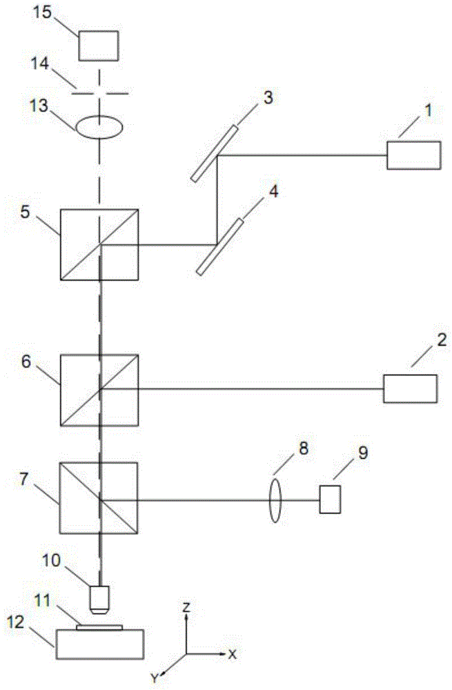
[0035] Step 1) The first beam of laser light 1 is reflected by the first reflector 3 and the second reflector 4 in turn, and transmitted to the objective lens 10 through the second beam splitter 6, and the second beam of laser light 2 is directly incident on the first On the two beam splitters 6, and through its reflection, the first beam of laser light 1 passes through the light transmitted by the second beam splitter 6 to synthesize a bunch of light rays that cannot be distinguished by naked eyes, pass through the objective lens 10, and converge to the said second beam splitter 6. At the focal point of the objective lens 10;

[0036] Step 2) select a particle 11 and place it on the focal plane of the objective lens 10, the incident light that cannot be distinguished by the naked eye converges on the particle 11 through the objective lens 10 to form a focused spot, and the particle 11 is a transparent carrier, S...


PUM


Abstract

The invention discloses a coaxiality adjusting method of multiple beams. The method comprises the following steps that: step (1), a plurality of reflectors or beam splitters are arranged at light paths of a plurality of laser light sources, so that light emitted by the multiple laser light source is combined into one beam of light that can not be distinguished by naked eyes; step (2), a particulate matter that can reflect laser is selected, wherein the particle size of each particle of the particulate matter is less than the diameter of the light spot of the light beam that can not be distinguished by naked eyes; step (3), with an imaging device arranged at a confocal laser scanning microscope, scanning imaging is carried out on the particulate matter by the light beam that can not be distinguished by naked eyes; and step (4), if the obtained image contains a double image, the light beam that can not be distinguished by naked eyes is not a coaxial one, and the reflectors or beam splitters are adjusted and the step (3) is carried out again; and if no double image exists in the obtained image, the light beam that can not be distinguished by naked eyes is the coaxial one and thus adjustment is completed.

Description

technical field [0001] The invention relates to the technical field of laser scanning confocal microscopic imaging, in particular to a multi-beam coaxial detection and adjustment method. Background technique [0002] Laser scanning confocal microscope (Confocal laser scanning microscope, CLSM) uses laser as the scanning light source, fast scanning and imaging point by point, line by line, and surface by line. The scanning laser and fluorescence collection share an objective lens. The focus of the objective lens is the focal point of the scanning laser. , is also the object point of the instantaneous imaging. After the system is focused once, the scanning is limited to one plane of the sample. When the focusing depth is different, the image information of different depth levels of the sample can be obtained. The image information is received by the imaging device and stored in the computer. Through computer analysis and simulation, the three-dimensional structure of the samp...

Claims


Application Information

Patent Timeline
Patent Type & Authority Applications(China)
IPC IPC(8): G01M11/00
Inventor 杨皓旻张运海
Owner SUZHOU INST OF BIOMEDICAL ENG & TECH CHINESE ACADEMY OF SCI
Why Eureka
Try Eureka