Tritium trap device used for removing tritium in helium-3 gas, and tritium-removing method

A gas and tritium trap technology, applied in the field of tritium trap devices, can solve the problems of difficult capture and protection of radioactive tritium, and achieve the effects of high safety, improved service life and guaranteed purity

Inactive Publication Date: 2015-04-22
NUCLEAR POWER INSTITUTE OF CHINA
View PDF10 Cites 8 Cited by
  • Summary
  • Abstract
  • Description
  • Claims
  • Application Information

AI Technical Summary

Problems solved by technology

[0006] The purpose of the present invention is to solve the problem that the radioactive tritium produced in the existing helium-3 circuit is difficult to capture and protect, and to provide a tritium for removing tritium in the helium-3 gas for the fuel element power transient test helium-3 circuit Trap device, the present invention also provides a method for removing tritium in a tritium trap device for removing tritium in helium-3 gas

Method used


Image

  • Tritium trap device used for removing tritium in helium-3 gas, and tritium-removing method

Examples


Embodiment 1

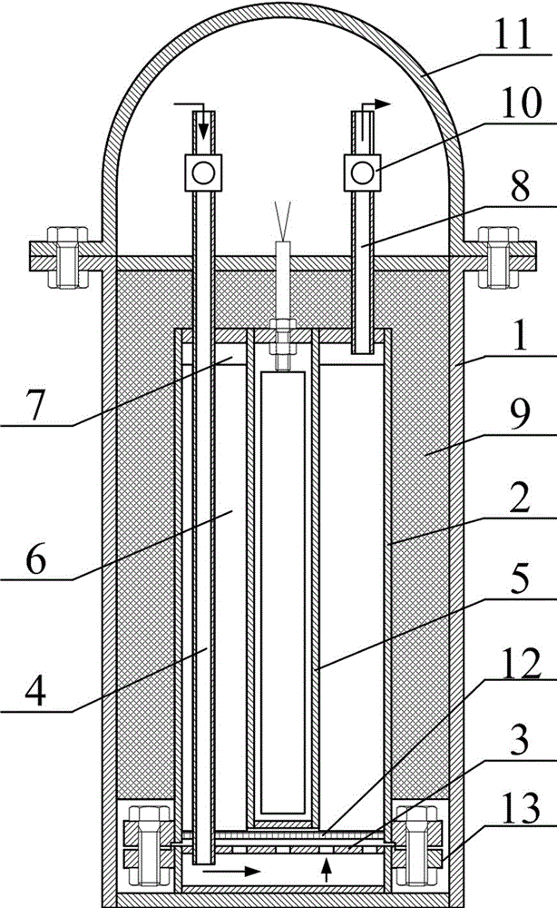
[0038] A tritium trap device for removing tritium from helium-3 gas, such as figure 1 As shown, it includes an outer shell 1, an inner shell 2 located inside the outer shell 1, an air inlet pipe 4 whose air outlet port is located below the inner shell 2, and a heating element fixed inside the inner shell 2. The cavity 5 is arranged above the gas outlet port of the inlet pipe 4 and filled with the titanium sponge 6 between the heating cavity 5 and the inner shell 2, and the titanium sponge 6 is arranged inside the inner shell 2 and is located above the titanium sponge 6 The reserved space 7, and the air outlet pipe 8 whose inlet port is located in the reserved space 7 for expansion.

[0039] Wherein, in the present embodiment, the outer shell 1 and the inner shell 2 are all arranged in a cylindrical shape, and the thickness of the titanium sponge 6 between the inner shell 2 and the heating cavity 5 is set to a thinner state, which is conducive to heating. The uniformity of tra...

Embodiment 2

[0052] The difference between this embodiment and Embodiment 1 is that this embodiment adds some auxiliary structures to achieve better results. The specific setting method is as follows:

[0053] The space between the outer shell 1 and the inner shell 2 is set in vacuum or / and filled with insulating material 9 . That is to say, the space between the outer shell 1 and the inner shell 2 in the present invention can only be set in vacuum, or only filled with heat-insulating material 9 , and can also be filled with heat-insulating material 9 while being set in vacuum. In this embodiment, the structure between the outer shell 1 and the inner shell 2 is preferably set in a vacuum setting and filled with insulating material 9 at the same time. That is, in this embodiment, a microporous calcium silicate heat insulating layer is placed between the outer shell 1 and the inner shell 2, and a certain vacuum is drawn to increase its heat insulating effect and reduce tritium leakage. Thro...

Embodiment 3

[0056] The difference between this embodiment and Embodiment 1 or Embodiment 2 is that this embodiment optimizes the specific structural settings in the inner shell, so that the distribution of the gas passing into the titanium sponge is more uniform, and the specific settings are as follows:

[0057] In this embodiment, the inner bottom of the inner shell 2 is provided with a gas distributor 3 , and the gas distributor 3 is located below the titanium sponge 6 and above the gas outlet port of the inlet pipe 4 . A wire mesh 12 for placing the titanium sponge 6 is arranged above the gas distributor 3 .

[0058] The gas outlet port of the air inlet pipe 4 extends from the top of the outer shell 1 into the inner shell 2 and penetrates the titanium sponge 6 from the top of the inner shell 2 and then extends to the bottom of the gas distributor 3 .

[0059] After the helium-3 gas in the present invention is distributed by the gas distributor 3, it is effectively and evenly dispersed...


PUM


Abstract

The invention discloses a tritium trap device used for removing tritium in helium-3 gas, and a tritium-removing method. The tritium trap device comprises an outer housing, an inner housing positioned inside the outer housing, a gas inlet pipe with a gas outlet port positioned in a lower part inside the inner housing, a heating chamber fixed inside the inner housing, a titanium sponge arranged above the gas outlet port of the gas inlet pipe and filled between the heating chamber and the inner housing, an expansion reserved space arranged inside the inner housing and positioned above the titanium sponge, and a gas outlet pipe with a gas inlet port positioned in the expansion reserved space. The invention also comprises a method for removing tritium with the tritium trap device. The device is suitable for removing tritium in a high-temperature high-pressure helium-3 loop, and has the advantages of reliable performance and compact structure. Also, with the device, heat loss and tritium permeation amount can be reduced. The device and the method have important significance in ensuring the safety and successful running of a power sharp-increase test.

Description

technical field [0001] The invention relates to a tritium trap device, in particular to a tritium trap device for removing tritium in helium-3 gas, and a method for removing tritium in helium-3 gas by using the tritium trap device. Background technique [0002] Over the lifetime of a nuclear power plant, fuel element power jumps may occur locally or overall due to reactivity control. For high burnup fuel structures, the components will not be damaged during the steady-state irradiation test, but damage may occur under the condition of power jump. Therefore, the in-stack transient behavior test of fuel elements is an important step to study the integrity of high-performance fuel assemblies under Class I and II operating conditions. [0003] The helium-3 loop is an important part of carrying out the safety and reliability test of high-performance fuel elements under the condition of power jump. This kind of test is impossible to carry out on the power reactor. The general met...

Claims


Application Information

Patent Timeline
Patent Type & Authority Applications(China)
IPC IPC(8): G21F9/02G21F9/30
CPCG21F9/02G21F9/007
Inventor 李炳林孙胜汪海戴钰冰杨文华聂良兵
Owner NUCLEAR POWER INSTITUTE OF CHINA
Why Eureka
Try Eureka