Eureka AIR delivers breakthrough ideas for toughest innovation challenges, trusted by R&D personnel around the world.

Rapid switching device for 110kV power system of petrochemical enterprises

A fast switching and power system technology, applied in the direction of power network operating system integration, circuit devices, information technology support systems, etc., can solve the difference of fast switching devices, the difference in the decay speed of the residual voltage of the voltage-loss bus, and the safety of large-scale electrical equipment cannot be guaranteed and other issues to achieve the effect of improving processing speed and avoiding production stoppage

Inactive Publication Date: 2015-04-22
CHINA PETROCHEMICAL CORP
View PDF0 Cites 5 Cited by
  • Summary
  • Abstract
  • Description
  • Claims
  • Application Information

AI Technical Summary

Problems solved by technology

However, since the power system of petrochemical enterprises contains large-scale electrical equipment such as generators and synchronous motors, it is quite different from the type of factory electrical equipment. For example, the motors used in factories are asynchronous motors. The fast switching device of the factory power backup power supply cannot guarantee the safety of the above-mentioned generators, synchronous motors and other large electrical equipment when switching
[0021] In addition, there are many large-capacity fans, compressors and other equipment inside the petrochemical system. These devices are loads with large moment of inertia. There is a large difference in speed, and there are also differences in the settings of the fast switching device and the factory power.

Method used


Image

  • Rapid switching device for 110kV power system of petrochemical enterprises
  • Rapid switching device for 110kV power system of petrochemical enterprises
  • Rapid switching device for 110kV power system of petrochemical enterprises

Examples


Embodiment Construction

[0052] Combine below Figure 3-6 The present invention is described further:

[0053] The present invention is used for the fast switching device of petrochemical enterprise 110kV electric power system, comprises:

[0054] Signal acquisition module: used to collect voltage Ua, Ub, Uc, current Ia, Ib, Ic, power Pa, Pb, Pc, frequency fa, fb, fc, incoming line switch 1DL and incoming line protection device 4DL on the incoming line Status signal and faulty bus voltage, current signal and voltage signal of backup power supply;

[0055] Data conversion module: convert the output of the signal acquisition module into a digital signal that can be recognized by the microcomputer chip;

[0056] Microcomputer chip: judge according to the digital signal and send jumping line switch command and switching command;

[0057] Opening and closing actuator: after receiving the jumping line switch command from the microcomputer chip, perform the operation of tripping the incoming line switch, ...


PUM


Abstract

Provided is a rapid switching device for a 110kV power supply system of petrochemical enterprises. The rapid switching device comprises a microcomputer chip, and the microcomputer chip determines whether a reverse power starting condition, a zero-current starting condition, a voltage-loss starting condition, a tripping error starting condition and a protection starting condition are satisfied; if the tripping error condition is satisfied, a switching operation is started, and whether the other conditions are satisfied are further determined successively; if any condition except the tripping error condition is satisfied, an incoming switch tripping command is emitted, the switching operation is started, and whether a rapid switching condition, a same-period capture switching condition, a residual voltage switching condition and a long delay switching condition are satisfied is determined successively; if one of the condition is satisfied, determination is stopped, and a corresponding switching command, namely a rapid switching command or a same-period capture switching command or a residual voltage switching command or a long time delay switching command, is transmitted. Thus, the 110kV power supply system of petrochemical enterprises can be stably switched between a working power supply and a standby power supply.

Description

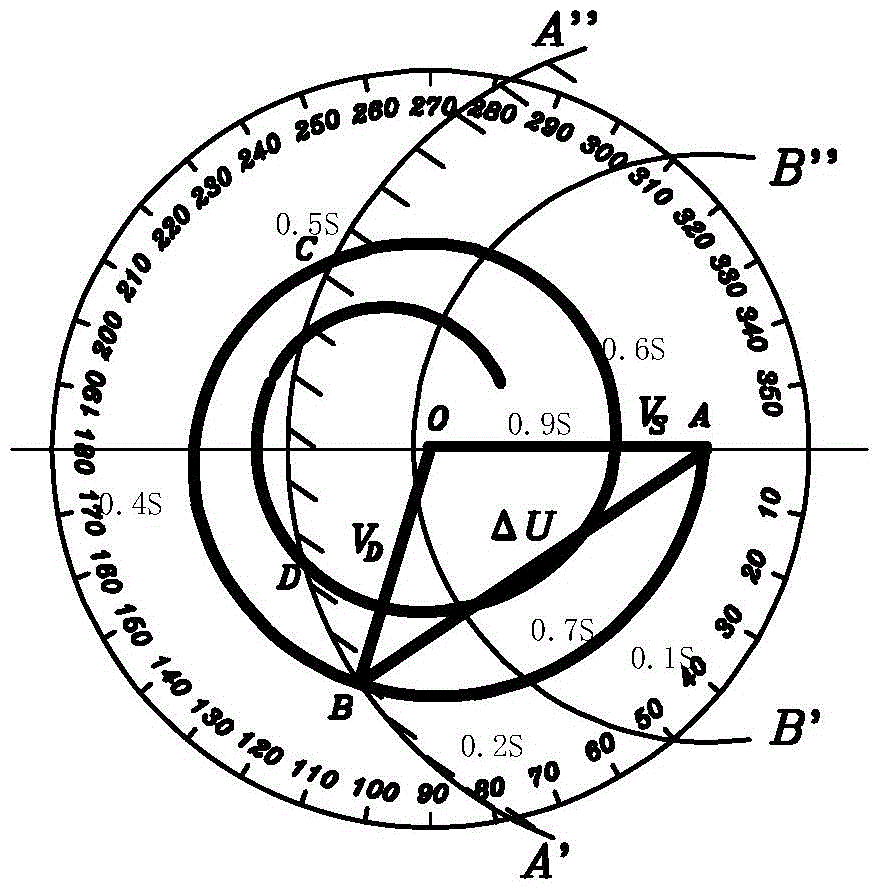
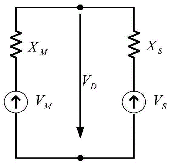
technical field [0001] The invention relates to a fast switching device used in a 110kV power system of a petrochemical enterprise. Background technique [0002] The traditional standby automatic switching method is to switch on the backup power supply by detecting the residual voltage on the line after the external line trips due to a fault such as lightning strike. [0003] Such as figure 1 It is a schematic diagram of the 6KV bus residual voltage characteristics of a 300MW unit, V D is the residual voltage of the busbar, the arc ABCD indicates the phasor change trajectory of the residual voltage of the busbar, and △U is the differential pressure between the backup power supply voltage and the residual voltage of the busbar. [0004] For the convenience of analysis, we take a power system and a single motor as an example, fully simplify the equivalent circuit of the backup power system and the motor according to the transient analysis model, ignore the winding resistance...

Claims


Application Information

Patent Timeline
Patent Type & Authority Applications(China)
IPC IPC(8): H02J9/06
CPCH02J9/06Y02B70/30Y04S20/20
Inventor 唐海东李宏湘邹国铖胡庭枝江明基高清茂
Owner CHINA PETROCHEMICAL CORP
Why Eureka
Eureka Blog
Learn More