A forming device and method for a thin-walled sleeve-like magnetic material

A magnetic material and molding device technology, applied in the field of powder metallurgy molding, can solve the problems of mold deformation, cracks, affecting the pressing power, etc., and achieve the effect of strengthening the pressure bearing capacity

Active Publication Date: 2017-01-11
PINGHU GEOR CHI ELECTRONICS CO LTD
View PDF6 Cites 0 Cited by
  • Summary
  • Abstract
  • Description
  • Claims
  • Application Information

AI Technical Summary

Problems solved by technology

However, for the production of thin-walled magnetic rings, due to the thin wall thickness of thin-walled magnetic rings, when performing powder compaction, due to the large unit area of ​​pressing, it is difficult for ordinary molds to withstand more than 500 MPa in terms of structure and materials. At the same time, it bears a large pressing area, which can easily cause uneven distribution and even cracks of the soft magnetic material in the pressed blank, and easily cause deformation or even fracture of the mold, which greatly affects the success rate of pressing and increases the cost of pressing

Method used


Image

  • A forming device and method for a thin-walled sleeve-like magnetic material
  • A forming device and method for a thin-walled sleeve-like magnetic material

Examples


Embodiment 1

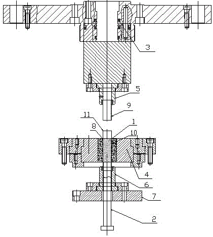
[0023] Such as figure 1 The schematic structural diagram of the forming device for the thin-walled sleeve-like soft magnetic composite material shown, including a powder forming machine and a pressing die.

[0024] Among them, the powder molding machine includes a frame and a powder feeder. A cylinder (3) is installed on the upper end of the frame, and the cylinder (3) is a pressurized cylinder (3) driven downward, and the rod core (2) in the mold is driven to move in the vertical direction by the pressurized cylinder (3).

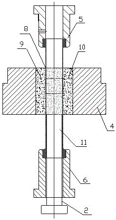
[0025] Such as figure 2 The schematic diagram of the mold structure of the molding device for the thin-walled sleeve soft magnetic composite material shown, including the rod core (2), the female mold (4), the upper punch (5), the lower punch (6) and the mold base (7) , at the same time, punching holes (8) are provided in the middle of the female die (4) and the upper and lower dies (6). The rod core (2) is perpendicular to the pressing direction of th...

Embodiment 2

[0027] Such as figure 1 The schematic structural diagram of the forming device for the thin-walled sleeve-like soft magnetic composite material shown, including a powder forming machine and a pressing die.

[0028] Among them, the powder molding machine includes a frame and a powder feeder. A cylinder (3) is installed on the upper end of the frame, and the cylinder (3) is a pressurized cylinder (3) driven downward, and the rod core (2) in the mold is driven to move in the vertical direction by the pressurized cylinder (3).

[0029] Such as figure 2 The schematic diagram of the mold structure of the molding device for the thin-walled sleeve soft magnetic composite material shown, including the rod core (2), the female mold (4), the upper punch (5), the lower punch (6) and the mold base (7) , at the same time, punching holes (8) are provided in the middle of the female die (4) and the upper and lower dies (6). The rod core (2) is perpendicular to the pressing direction of th...


PUM


Abstract

The invention provides a forming device and a forming method for thin-wall sleeve magnetic materials, and relates to the field of powder metallurgy forming. The device comprises a powder forming machine and a pressing die; the fit clearance between a lower punch of the die and the inner wall of a punching hole is 5-8mum, and the fit clearance between an upper punch of the die and the punching hole is 5-8mum; the strength of a material adopted by effective working parts of a rod core, the upper punch and the lower punch, and a female die are respectively higher than the saturation polarization strength of soft magnetic material powder which needs to be pressed; tungsten steel of which the compressive strength is more than HRA89 degrees is adopted by the effective working parts of inner walls of the upper punch and the lower punch and the rod core; high-speed steel is adopted by the female die and a substrate of the pressing die, i.e. the upper punch and the lower punch are both of welding structures of the tungsten steel and the high-speed steel. According to the forming device and the forming method provided by the invention, the pressing effect of the soft magnetic powder is enhanced, so that the density of all parts of a formed thin-wall sleeve is uniform, and the thin-wall sleeve has higher dimensional accuracy.

Description

technical field [0001] The invention belongs to the technical field of powder metallurgy molding, and in particular relates to a molding device and method for thin-walled sleeve magnetic materials. Background technique [0002] Soft magnetic composite (Soft Magnetic Composite, SMC) is manufactured by powder metallurgy technology. It is composed of surface insulating metal powder particles (such as iron powder, NdFeB alloy powder), and can be pressed into parts with complex shapes in one step, and has good The three-dimensional isotropic magnetic properties, as well as the low eddy current loss at medium and high frequencies, can be used as iron core materials in some motors with complex shapes and magnetic circuits and motors working at higher frequencies, and can be widely used and at the same time Revolutionizing power motor design. With the development of miniaturization and high frequency of electronic devices, micro-motors, low-power motors and anti-electromagnetic int...

Claims


Application Information

Patent Timeline
Patent Type & Authority Patents(China)
IPC IPC(8): B22F3/03B22F1/00
Inventor 钟远东李伟平李叶亮房建明陈善华罗合兵邹海平
Owner PINGHU GEOR CHI ELECTRONICS CO LTD
Why Eureka
Try Eureka