Spinning assembly

A technology for spinning components and threads, applied in the field of spinnerets, can solve the problems of reduced component life, deviation of polymer spinning amount, and reduced impurity trapping ability, and achieves the effect of inhibiting deterioration and uniform thermal process.

Inactive Publication Date: 2015-04-29
TMT MACHINERY INC
View PDF13 Cites 5 Cited by
  • Summary
  • Abstract
  • Description
  • Claims
  • Application Information

AI Technical Summary

Problems solved by technology

As a result, in some of the above-mentioned filters, the impurity trapping ability is reduced early, so the life of the components is re

Method used


Image

  • Spinning assembly
  • Spinning assembly
  • Spinning assembly

Examples


Embodiment Construction

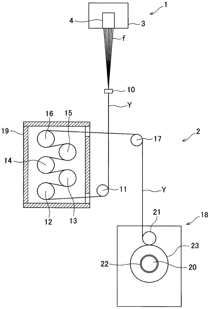
[0057] Next, embodiments of the present invention will be described. figure 1 It is a schematic configuration diagram of the melt spinning device 1 and the spinning take-up machine 2 that winds the yarn Y spun from the melt spinning device 1 according to the present embodiment. Additionally, the figure 1 The up and down direction of is defined as the up and down direction of the melt spinning device 1 and the spinning tractor 2. First, the schematic configuration of the melt spinning device 1 and the spinning drawer 2 will be described.

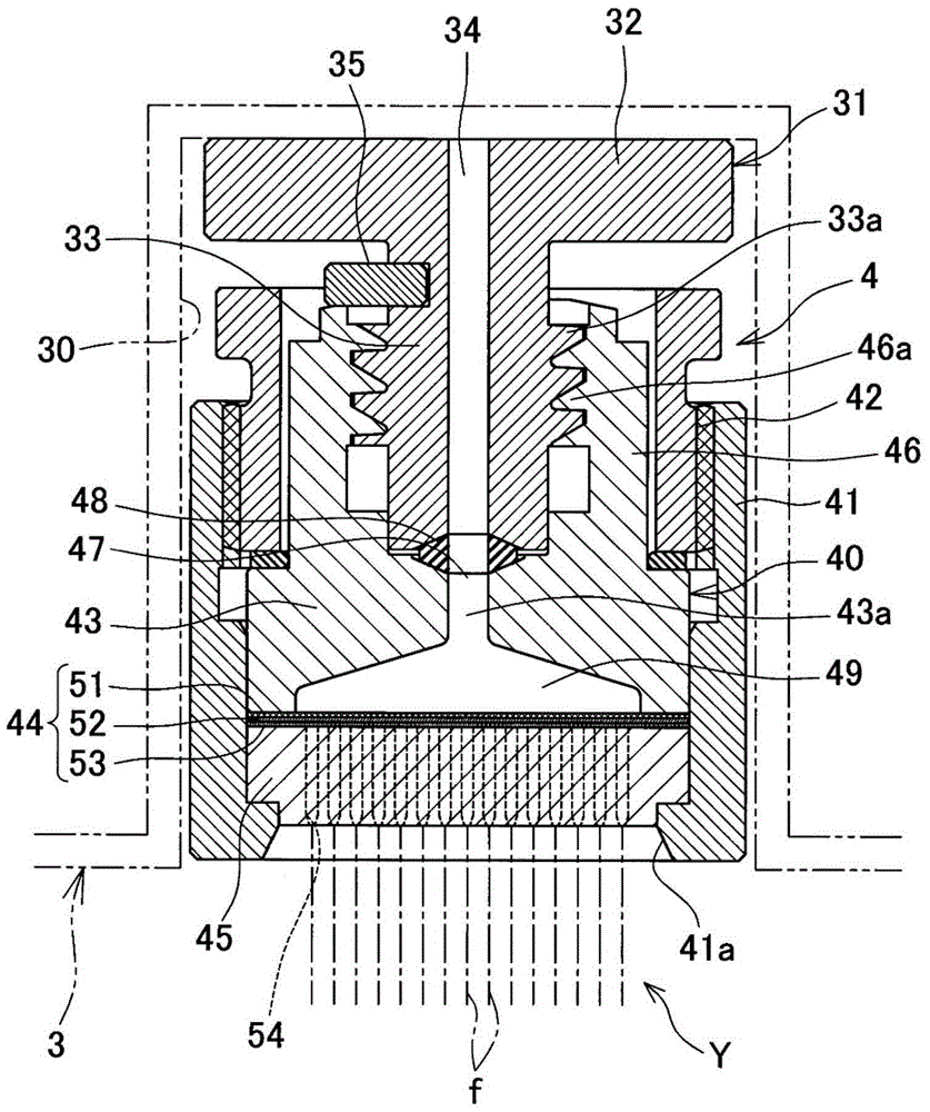
[0058] The melt spinning device 1 includes a heating box 3 and a plurality of spinning packs 4 detachably attached to the heating box 3 . Multiple spin packs 4 along figure 1 Arranged side by side in the vertical direction of the paper. A yarn Y composed of a plurality of single fibers f is spun downward from each spin pack 4 . The structure of the melt spinning device 1 including the spinning pack 4 will be described in detail later.

...


PUM

PropertyMeasurementUnit
Viscosityaaaaaaaaaa

Abstract

The invention provides a spinning assembly. In a spinning assembly without using granulous filtering materials, sufficient refining of gel-shaped parts of polymer, reduction of residence time of the polymer in the assembly and uniformization of spun-out volume of the polymer among multiple nozzles are achieved. The spinning assembly (4) is provided with a polymer flowing-in part (43), a filter (44) and a spinning nozzle (45). The polymer flowing-in part is provided with a guiding-in part (47) with to-be-guided-in fused polymer and a buffering space (49) directly connected to the guiding-in part (47) via a polymer supplying hole (43a). The filter is disposed to the lower part of the buffering space (49). The spinning nozzle is connected with the filter (44) and multiple nozzles (54) for separately spinning out fused polymers passing through the filter (44) are formed on the spinning nozzle (45). The filter (44) also comprises a first filtering layer (51) which is formed via sintering of metal short fibers with polygonal cross sections.

Description

technical field [0001] The present invention relates to a spinning pack including a spinneret for spinning molten polymer. Background technique [0002] Conventionally, there is known a melt spinning device for spinning synthetic fiber yarns. A general melt spinning device has a detachable spinning unit. The heated molten polymer is supplied to the spin pack, and the molten polymer is spun out from a plurality of nozzles of the spin pack to form a plurality of single fibers. The spin pack usually has a filter material that filters the molten polymer. [0003] Patent Document 1 discloses a general spinning pack having a granular filter material such as sand. The spinning pack has a polymer inlet, a granular filter material, a filter, a spinneret, and the like. Inside the spin pack, a space is provided below the polymer inlet, and the lower part of the space is filled with a granular filter material. The molten polymer introduced into the space from the polymer inlet is s...

Claims


Application Information

Patent Timeline
IPC IPC(8): D01D1/06D01D1/10D01D4/02
CPCD01D1/06D01D1/106D01D4/02
Inventor 川本和弘松井正宏
Owner TMT MACHINERY INC
Why Eureka
Try Eureka