Reinforced concrete frame gridding slab prefabricated energy-saving house

A technology of reinforced concrete and prefabricated assembly, which is applied in the direction of construction and building construction, which can solve the problems of difficult movement, repeated use, inability to dismantle, difficult transportation and installation, etc., and achieve the effect of lightweight full assembly

Inactive Publication Date: 2015-04-29
徐曼
View PDF5 Cites 34 Cited by
  • Summary
  • Abstract
  • Description
  • Claims
  • Application Information

AI Technical Summary

Problems solved by technology

Assembled a monolithic concrete structure house, which has good integrity, but cannot be dismantled, and is difficult to move and reuse
The prefabricated wall panels of existing prefabricated buildings mostly use solid concrete wall panels, which have defects such as heavy weight, difficult transportation and installation, and poor thermal insulation effect

Method used


Image

  • Reinforced concrete frame gridding slab prefabricated energy-saving house
  • Reinforced concrete frame gridding slab prefabricated energy-saving house
  • Reinforced concrete frame gridding slab prefabricated energy-saving house

Examples


Embodiment 1

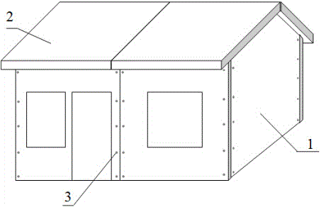
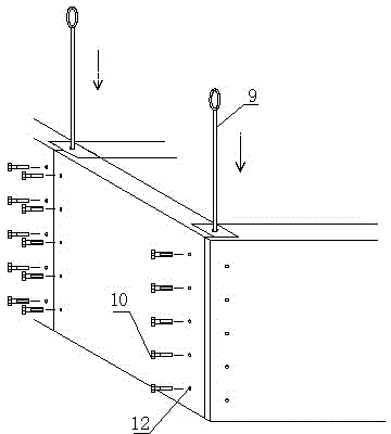
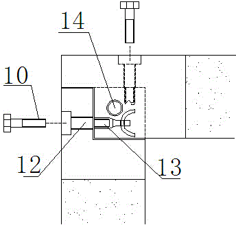
[0056] Embodiment 1: (single-storey house embodiment with sloping roof) see Figure 1-6 , figure 1 An axonometric drawing of a prefabricated house. The house is composed of a sash concrete lightweight wall panel (1), a sash concrete roof panel (2) and connecting fittings (3). figure 2 It is the dismantling diagram of the components of Example 1, (4) is the sash assembled lightweight wall panel, (5) is the sash roof panel, and the sash concrete wall panel and the floor slab roof panel are surrounded by different types of bites ( 6) The reinforced concrete slab frame (7) and the foam concrete (8) in the slab frame frame are composed. After the two slabs are interlocked and occluded, they are tied by the long pin bars (9) and fixed by the fixing bolts (10). The shear pin block (11) is used to improve the shear resistance of the seam. image 3 , Figure 4 It is a fixing method after two (or 3) wallboards are occluded. After the occlusal, the vertical reserved holes of the o...

Embodiment 2

[0057] Embodiment 2 (manufacturing method 1 of sash wall panel and floor slab roof panel), see Figure 7 - 9, Figure 7 It is the assembly diagram of the combined mold for the prefabrication of sash concrete wall panels and floor slab roof panels. The combined mold is mainly composed of a surrounding frame (19) (20) and a bite module (21) (22) fixed on the surrounding frame. Figure 8 is a schematic diagram of the combined abrasive tool bite module (22), the bite module is fixed (or welded) on the surrounding frame with fixing bolts, and the foam concrete block (23) is placed in the plate frame surrounded by the combined mold, and fixed at the design position Hole-reserved plastic pipe (24) (25), fix the pre-embedded fixture with internal thread on the mold, and the plastic pipe (24) with the reserved pin hole passes through the long steel bar (26) passing through the bite module and the plastic pipe )fixed. Figure 8 It is a schematic diagram of the reinforcement of the s...

Embodiment 3

[0058] Embodiment 3 (the manufacturing method of sash wall panels and floor slab roof panels) see Figure 10-11 , Figure 10 It is a schematic diagram of a reinforced concrete frame frame. The foam concrete block (23) in Example 2 is replaced by a formwork. First, a frame (31) with a bite (30), a longitudinal rib (32), and a transverse rib ( 33) The reinforced concrete sash frame (7) formed, forms the gap (34) between the concrete sash after the formwork is removed. Figure 11 It is a schematic diagram of pouring foam concrete into the gap of the frame. After the concrete slab (7) is cured to a certain strength, a low surrounding formwork (34) is made on the outer edge of the outer frame, and the foam concrete (35) is poured into the slab. Foamed concrete can be used as a reinforced insulation layer (36) covering the entire slab surface by a certain thickness higher than the slab frame, Figure 10 .


PUM


Abstract

The invention relates to a reinforced concrete frame gridding slab prefabricated energy-saving house. The reinforced concrete frame gridding slab prefabricated energy-saving house is assembled by prefabricated frame gridding concrete wallboards, floor slabs, roof boards, prefabricated frame gridding concrete foundation section and accessories, wherein the prefabricated slabs are formed in a mutually mechanical occlusion and connection manner; the prefabricated slabs are fixed by means of fixing bolts, pin ribs or post-tensioned prestressed reinforcements; a frame gridding type concrete slab frame is a #-shaped reinforced concrete load-bearing frame consisting of longitudinal and horizontal ribs; each of four sides of the slab frame is provided with mechanical connection connectors, and preformed holes or is provided with pre-embedded connecting pieces; two surfaces or one surface of each slab of the slab frame are / is covered with a heat insulating material, a decorative finish layer or a concrete protecting layer. The reinforced concrete frame gridding slab prefabricated energy-saving house realizes light weight, full assembly as well as disassembly and shift availability of a house with a prefabricated concrete structure.

Description

technical field [0001] The invention belongs to the field of environment-friendly and energy-saving prefabricated house construction. Provided is a method for constructing a fully assembled, detachable, cage-type environment-friendly and energy-saving house that uses prefabricated reinforced concrete frame foundations, wall panels, floor slabs and roof panels, and is constructed through mechanical occlusal connections. Background technique [0002] At present, the construction methods of prefabricated houses mainly include light steel structure houses, wooden structure houses and assembled integral concrete structure houses. Light steel structure houses and wooden structure houses have great limitations in the firmness, durability, fireproof and waterproof performance of the houses, and they are not suitable for harsh environmental conditions such as the wild. Assembling a monolithic concrete structure house has good integrity, but it cannot be dismantled, and it is difficu...

Claims


Application Information

Patent Timeline
Patent Type & Authority Applications(China)
IPC IPC(8): E04B1/343E04B1/61
Inventor 徐曼徐学东马萍
Owner 徐曼
Why Eureka
Try Eureka