Universal single-cylinder large-displacement gasoline engine device
A gasoline engine, large displacement technology, applied in the direction of engine components, machines/engines, engine lubrication, etc., can solve problems such as the inability of single-cylinder engines to meet market demand, to prevent poor lubrication lock, reduce manufacturing costs, improve The effect of flyaway speed
- Summary
- Abstract
- Description
- Claims
- Application Information
AI Technical Summary
Problems solved by technology
Method used
Image
Examples
Embodiment 1
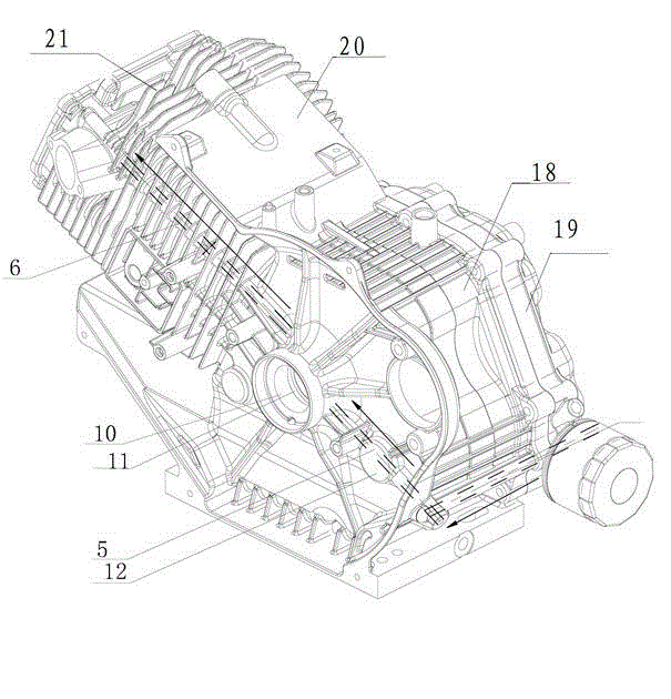
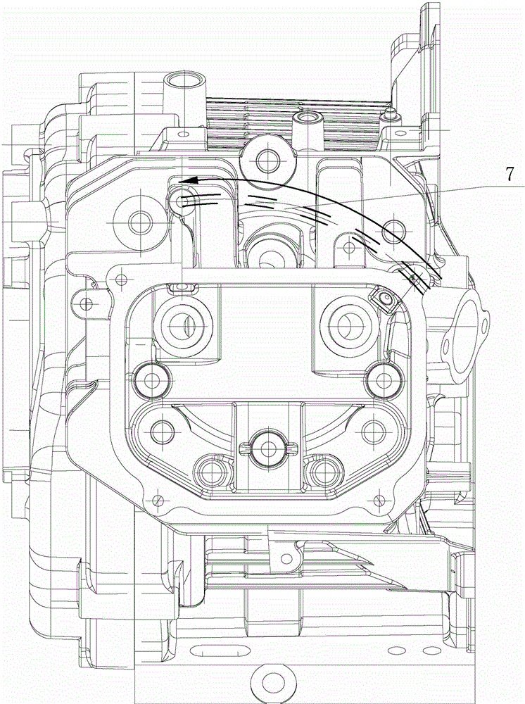
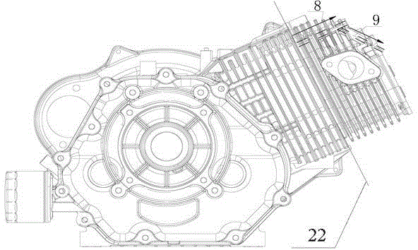
[0040] Embodiment one-to-one Figure 1~4 , the reference signs in the first embodiment include: oil passage A 1, oil passage B 2, oil passage C 3, oil passage D 4, oil passage E 5, oil passage hexa 6, oil passage G 7, oil passage Xin 8 , oil passage 9, box oil tank 10, box crankshaft hole 11, box balance shaft 12, box cover balance shaft 13, box cover oil tank 14, box cover crankshaft hole, oil pump 16, filter 17, box body 18 , Case cover 19, cylinder head 20, cylinder head cover 21, joint surface 22.
[0041] Oil passages are arranged on the engine casing 18, case cover 19, and cylinder head 20, and the oil passages are communicated by machining. The oil passes through the oil pump 16 and enters the filter 17 through the oil passage A 1. After that, the oil passage is divided into two branches. One branch is oil passage B 2. The oil passage B 2 is arranged on the tank cover 19. The oil passage B comes from the filter. 17 arrives at case cover oil groove 10, through the oil ...
Embodiment 2
[0044] Embodiment two corresponds to the attached Figure 5-7 , the reference signs in the second embodiment include: camshaft 1, limit boss 11, exhaust cam 2, intake cam 3, slider 4, bolt 41, counterweight 42, groove 43 in the middle of the slider , slide hole 5, push rod 6, stage clip 7.
[0045] Embodiment 2 includes all the content recorded in Embodiment 1, and also includes the following content. The camshaft is provided with an exhaust cam and an intake cam. The mechanism of this device is mainly located at the intake cam on the camshaft. It is in a C shape and hugged on the camshaft on the side of the intake lobe. The slider is located between the intake lobe and the limit boss 11 on the camshaft. The bolts that can be used for guiding pass through the slider up and down in parallel. side and camshaft, and fix the counterweight on the slider, because the bolt passes through the camshaft with a gap in the radial direction, under the guidance of the bolt, the slider can sl...
Embodiment 3
[0048] Embodiment three corresponds to the appended Figure 8-9 , The reference signs in the third embodiment include: support 1 , pin shaft 2 , rocker arm 3 , force end 4 , locking screw 5 , contact end 6 , pin shaft seat 7 , and screw hole 8 .
[0049] Embodiment 3 includes all the contents recorded in Embodiments 1 and 2, and also includes the following content. The rocker structure of this embodiment includes a support 1 and a rocker 3. The support 1 is a symmetrical structure. There are screw holes 8 to facilitate the fixing of the support 1 on the engine, and the two rocker arms 3 are symmetrically arranged on both sides of the symmetrical center line of the support 1, because the distance between the exhaust valve and the intake valve on the engine is usually greater than that of the push rod. The distance between them, therefore, the two rocker arms 3 are not parallel, such as figure 1 As shown, it is in an inverted "eight" shape, and the rocker arm 3 is an arc-shaped...
PUM
 Abstract
Description
Claims
Application Information
 - R&D
- Intellectual Property
- Life Sciences
- Materials
- Tech Scout
- Unparalleled Data Quality
- Higher Quality Content
- 60% Fewer Hallucinations
Browse by: Latest US Patents, China's latest patents, Technical Efficacy Thesaurus, Application Domain, Technology Topic, Popular Technical Reports.
© 2025 PatSnap. All rights reserved.Legal|Privacy policy|Modern Slavery Act Transparency Statement|Sitemap|About US| Contact US: help@patsnap.com


