
Axial flow fan for nuclear power station containment continuous ventilation system

A nuclear power plant containment and ventilation system technology, which is applied to the parts of pumping devices for elastic fluids, mechanical equipment, machines/engines, etc., can solve the problem of insufficient strength performance, unimaginable consequences, and axial displacement of blades and hubs To meet the performance requirements, strengthen the connection strength and improve the reliability

Inactive Publication Date: 2015-04-29
ZHEJIANG JINDUN FANS HLDG
View PDF6 Cites 10 Cited by
  • Summary
  • Abstract
  • Description
  • Claims
  • Application Information

AI Technical Summary

Problems solved by technology

However, the large axial flow fans currently on the market cannot meet the performance requirements of large flow and high static pressure in the continuous ventilation system of the containment of nuclear power plants.
Regardless of whether it is the aluminum alloy die-casting hub and blades commonly used in large axial flow fans, or the steel hub and blades, their strength and performance are far from meeting the requirements of the containment ventilation system.
Moreover, due to the defects in the structure, when using the Huff type hub and the blade to clamp, the torque on each bolt will be uneven, so that the axial movement of the blade and the hub will be relatively large, and it is difficult to control the relationship between the blade and the fan. Radial clearance; when the flanged hub and the blade are clamped, because the mounting surface of the hub is a circular arc, and the surface of the bolt fastener that matches it is a plane, the hub and the bolt fastener will contact in the form of points or lines Cooperate, the connection strength of the bolt cannot be guaranteed
However, when the fan is continuously running at high speed, it is subjected to huge centrifugal force, and if the connection strength between the blade and the hub cannot be guaranteed, it is prone to safety hazards
Once a safety accident occurs, the consequences will be disastrous

Method used


Image

  • Axial flow fan for nuclear power station containment continuous ventilation system
  • Axial flow fan for nuclear power station containment continuous ventilation system
  • Axial flow fan for nuclear power station containment continuous ventilation system

Examples


Embodiment Construction

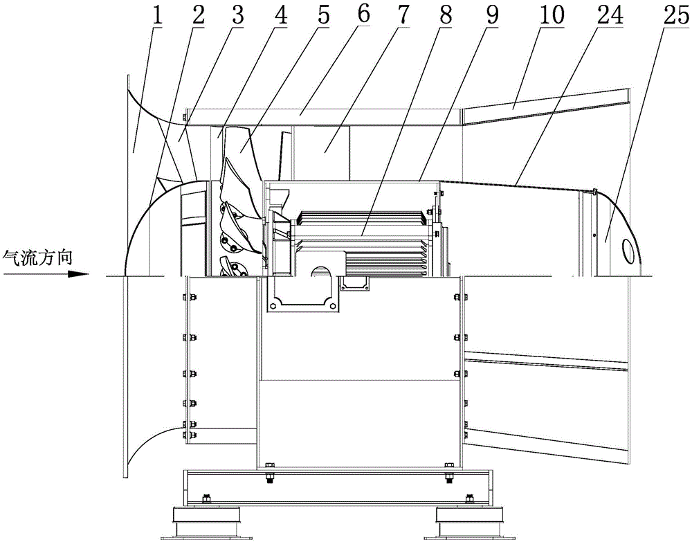
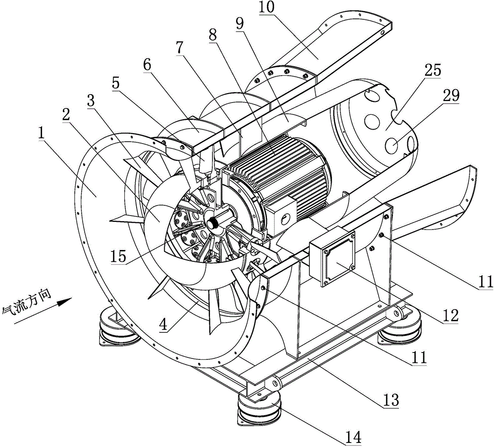
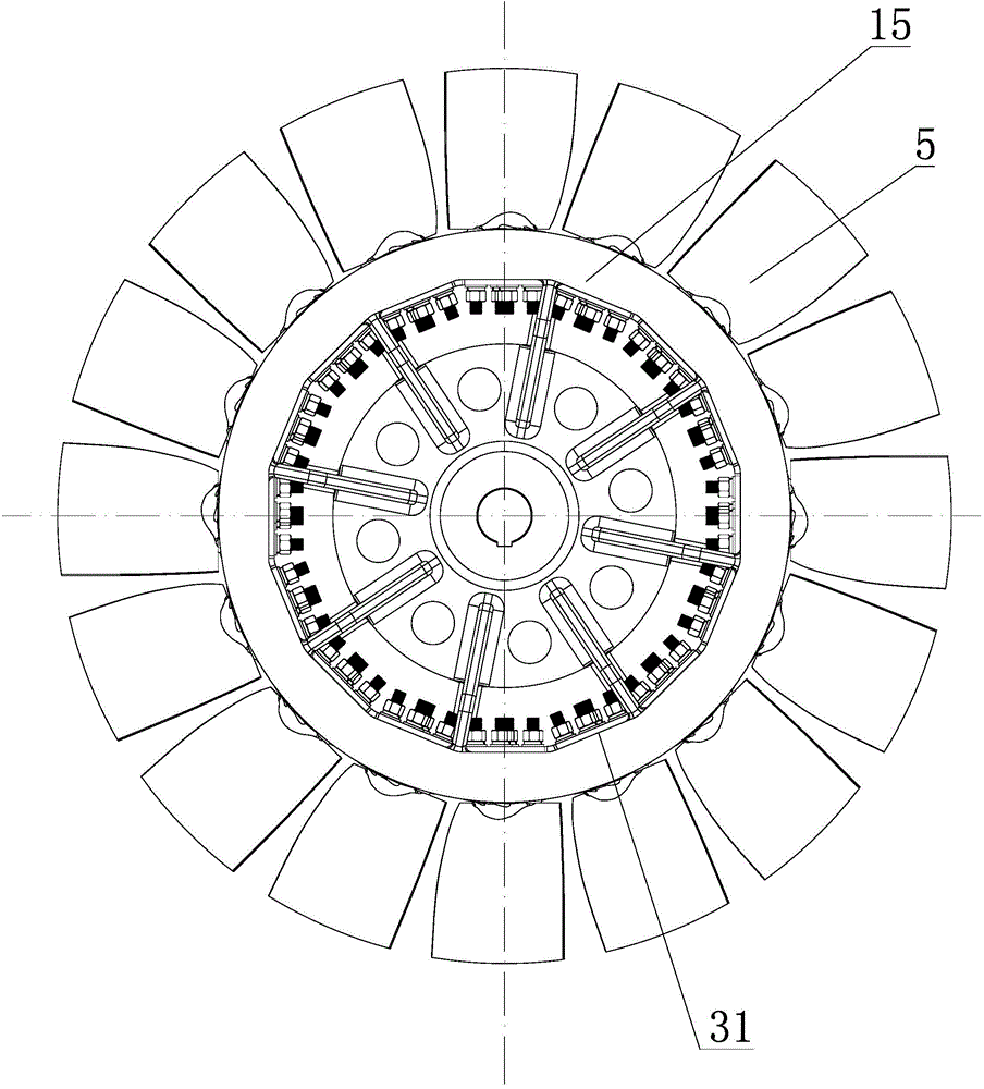
[0027] Such as figure 1 , figure 2 , image 3 , Figure 4 , Figure 5 As shown, an axial flow fan for a continuous ventilation system of a nuclear power plant containment according to the present invention includes a fairing 2, an impeller, and an inner cylinder assembly 9 arranged in sequence in the casing according to the airflow direction. The casing is composed of a current collector 1, a fan outer cylinder 6, and a diffuser cylinder 10 arranged in sequence according to the airflow direction. The current collector 1, the fan outer cylinder 6, and the diffuser cylinder 10 are fixedly connected by bolt fasteners. The fairing 2 is welded together with the collector 1 through the front inlet guide vane 3 . The inner cylinder assembly 9 includes a motor 8 installed in the cylinder, the impeller is installed on the output shaft of the motor 8 , and the outer wall of the cylinder is fixedly connected with the fan outer cylinder 6 through guide vanes 7 .

[0028] A further ...


PUM


Abstract

The invention relates to a high pressure axial flow fan applied to various high pressure axial flow ventilation system, particularly relates to an axial flow fan for a nuclear power station containment continuous ventilation system, and belongs to the technical field of axial flow fans. The fan comprises a fairing, an impeller and an inner barrel assembly which are arranged in a casing sequentially in the air flow moving direction. The casing is composed of a collector, a fan outer barrel and a diffuser which are sequentially arranged in the air flow moving direction. The fairing is fixedly connected with the collector through a front inlet guide vane. The inner barrel assembly comprises a motor installed in a barrel body, the impeller is installed on an output shaft of the motor, and the outer wall of the barrel body is fixedly connected with the fan outer barrel through the guide vane. The axial flow fan has the advantages of being high in efficiency, saving energy, being low in noise and high in stability and the like.

Description

technical field [0001] The invention relates to a high-pressure axial-flow fan, which is applied to various high-pressure axial-flow ventilation systems, and more specifically relates to an axial-flow fan for a nuclear power plant containment continuous ventilation system, which belongs to the technical field of axial-flow fans. Background technique [0002] Nuclear energy has become an important energy source used by human beings, and nuclear power is one of the important ways to solve energy shortage and environmental problems in our country. The development of nuclear power is an inevitable strategic choice for our country, but nuclear safety is the soul and core of the entire nuclear industry. Especially affected by the Fukushima nuclear leakage accident in Japan, national leaders and the National Nuclear Safety Administration put nuclear safety at the forefront of nuclear culture. As the last barrier in nuclear power plants to prevent the release of fission prod...

Claims


Application Information

Patent Timeline
Patent Type & Authority Applications(China)
IPC IPC(8): F04D25/08F04D29/02F04D29/32F04D29/54
CPCF04D25/08F04D29/023F04D29/325F04D29/541
Inventor 戴美军罗建平黄岳钬徐意根王洪厅
Owner ZHEJIANG JINDUN FANS HLDG
Learn More