Smokeless particle combustion machine

A burner and particle technology, which is applied in the direction of combustion method, combustion equipment, solid fuel combustion, etc., can solve the problems of insufficient combustion of combustion devices, low heat utilization efficiency, and the separation of net hot air and waste heat recovery devices, etc. , to achieve the effect of simple structure, high heat utilization efficiency and low smoke emission

Inactive Publication Date: 2015-04-29
DONGGUAN LIXIN AUTOMATIC SPRAYING EQUIP
View PDF6 Cites 1 Cited by
  • Summary
  • Abstract
  • Description
  • Claims
  • Application Information

AI Technical Summary

Problems solved by technology

[0004] However, the combustion of the combustion device is not sufficient, the heat utilization efficiency

Method used


Image

  • Smokeless particle combustion machine
  • Smokeless particle combustion machine
  • Smokeless particle combustion machine

Examples


Embodiment Construction

[0021] In order to enable the examiner to further understand the structure, features and other purposes of the present invention, the attached preferred embodiments are attached with accompanying drawings in detail as follows. The embodiments illustrated in the accompanying drawings are only used to illustrate the technical solution of the present invention , not to limit the present invention.

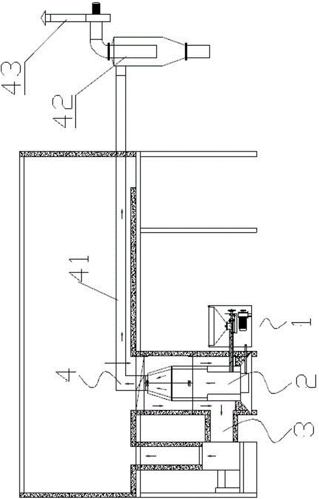
[0022] Such as figure 1 , a smokeless particle burner provided by the present invention, the smokeless particle burner includes a feeding device 1 , a burner 2 , a heat energy utilization system 3 and a waste heat recovery system 4 .

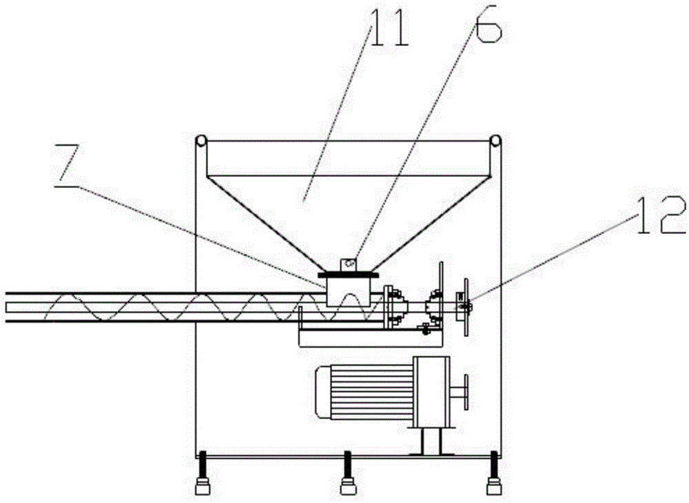
[0023] figure 2 As shown, the feeding device 1 includes a feeding hopper 11, and a screw automatic feeding device 12 at the bottom of the feeding hopper 11, and the screw automatic feeding device 12 extends to the burner 2;

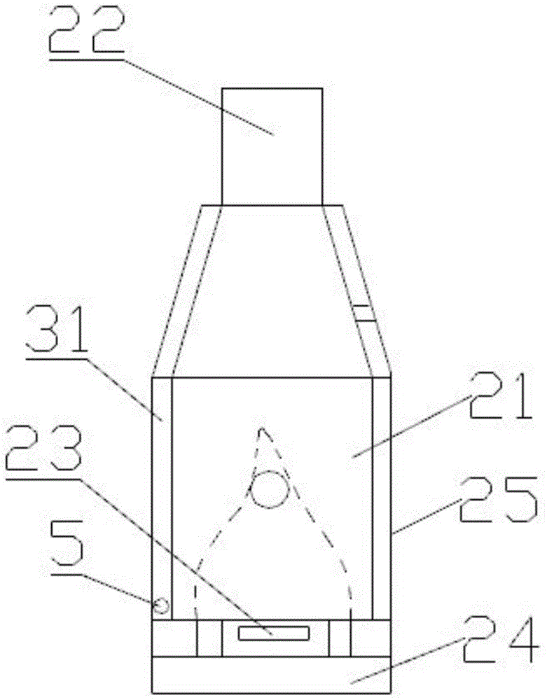
[0024] Such as image 3 The burner 2 shown includes a cyclone type combustion liner 21, the top of the liner 21 is provided w...


PUM


Abstract

The invention provides a smokeless particle combustion machine which comprises a feeding device, a combustion machine, a heat energy utilizing system and a waste heat recycling system. A circulating fan is connected with a heat channel formed between an inner container and an inspection door of the heat energy utilizing system and is connected to a drying oven; an exhaust fan of the waste heat recycling system is connected to an excess heat recycling pipeline, and the tail end of the excess heat recycling pipeline is connected to an induced draft fan by a cyclone separator. The smokeless particle combustion machine has the advantages of simple structure, sufficient combustion, high heat utilization efficiency and smokeless emission.

Description

technical field [0001] The invention relates to a combustion device, in particular to a combustion machine for burning biomass particle fuel. Background technique [0002] The structure of the existing biomass pellet burner has many defects such as automatic and accurate feeding, incomplete combustion, unreasonable oxygen distribution, and poor control of firepower, which leads to high labor intensity for operators. When the biomass is burned, there will be black smoke and a large amount of smoke and dust, which will seriously pollute the environment. [0003] Chinese patent CN 102589271 A discloses a pellet fuel burner including an ignition device, a blower, an inner tank, an outer tank, a feeding device, a drying furnace, a heat dissipation pipe, a circulating fan and an exhaust pipe. The ignition device has an ignition end, and the blower is connected with the ignition device. The ignition end is located in the inner tank. The inner tank is located in the outer tank an...

Claims


Application Information

Patent Timeline
IPC IPC(8): F23B40/00F23K3/14
Inventor 杨中敏
Owner DONGGUAN LIXIN AUTOMATIC SPRAYING EQUIP
Why Eureka
Try Eureka